HS50_advance_level 2.pdf - 第403页
Stud ent Gu ide HS-5 0 Adva nced II 07/2 002 Ed ition 14 Conve yor System 29

07/2002 Edition Student Guide HS-50 Advanced II
14 Conveyor System
28
➠ Remove the faulty conveyor belt from the guide channel for the movable side.
➠ Lift the conveyor belt out over the drive unit which has been removed.
,QVWDOOLQJWKH7RRWKHG%HOWIRUWKH0RYDEOH6LGHRIWKH&RQYH\RU
CAUTION O
The new toothed belt must not be stretched or kinked. 14
➠ Carry out DOOsteps as described in section 14.3.4.2 for the installation of the conveyor belt for
the fixed side but with the following differences:
➠ Lift the new conveyor belt in over the conveyor drive unit which has been removed.
➠ Place the new toothed belt in the guide channel of the movable conveyor side -> The con-
veyor belt must be engaged over its entire width.
➠ Adjust the guide rails (see section 14.3.7).
➠ Carry out the pertinent )LQDOVWHSVLQFOXGLQJIXQFWLRQFKHFN(see section 14.4).
For the function check, transport a PCB from the input or preceding station to the output or fol-
lowing station.
Student Guide HS-50 Advanced II 07/2002 Edition
14 Conveyor System
29

07/2002 Edition Student Guide HS-50 Advanced II
14 Conveyor System
30
Key to
([FKDQJLQJ+ROG'RZQ'HYLFHVDQGWKH&RPSUHVVLRQ6SULQJVIRU+ROG
'RZQ'HYLFHV
CAUTION O
Customers are not to loosen any screws (e.g., at the point of rotation of the rocking lever) which
have been secured with loctite. 14
5HPRYLQJ&RPSUHVVLRQ6SULQJVDQGRU+ROG'RZQ'HYLFHV
➠ Move the conveyor to PD[LPXPwidth so that you will be able to remove the lifting table plate
during a subsequent step.
➠ Move the Y-gantries into the area outside of the PCB conveyor.
➠ Turn the machine off at the main switch and disconnect the machine from the mains.
➠ Conscientiously secure the machine against reactivation during servicing work.
➠ Install the lifting table in the pertinent conveyor area, as described in section 14.3.8.1.
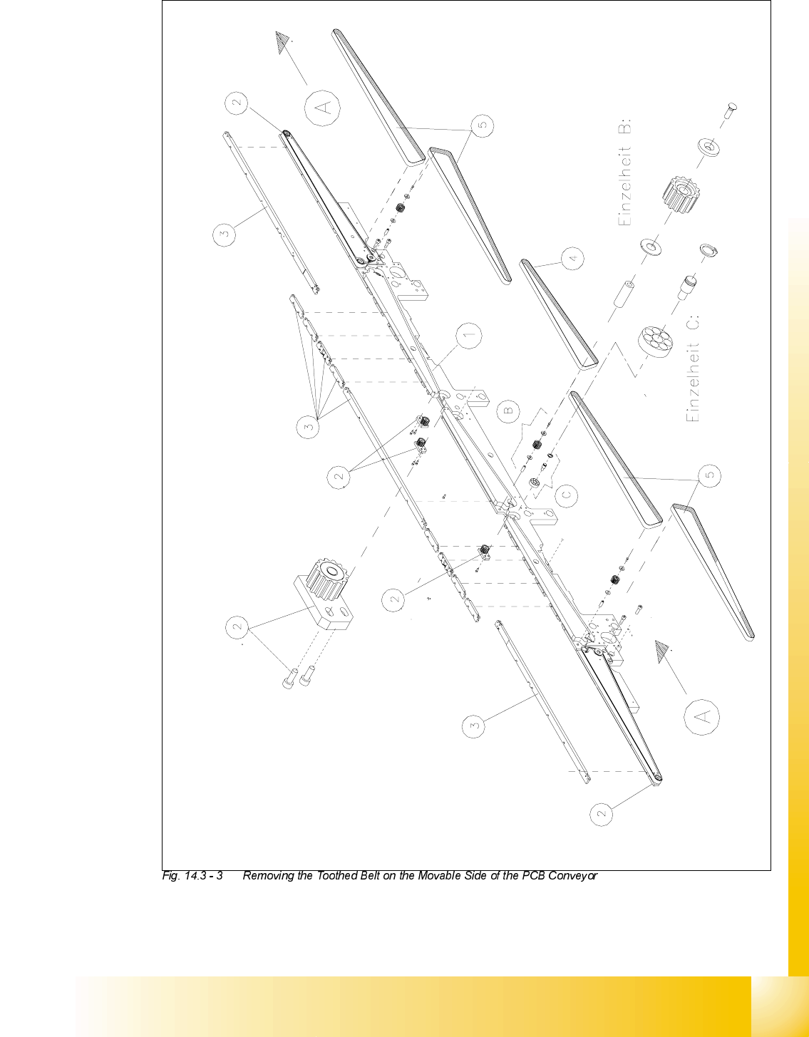
A) PCB transport direction B) Detail: conveyor toothed belt guide, syn-
chronizing disk
(Details: see Spare Parts Catalog)
C) Detail: bearing assembly of the hexagonal
drive shaft, end shield
(Details: see Spare Parts Catalog)
1) Movable side of conveyor (input to output
conveyor)
2) Belt guide, adjustable, fasteners are two
hexagonal socket head cap screws M3 x
10
3) PCB guide rails, fasten with M3 hexagonal
socket head cap screws
4) Toothed belt for intermediate conveyor
(fixed and movable side)
5) Toothed belt for all conveyor areas, except
intermediate conveyor
(fixed and movable side)