HS50_advance_level 2.pdf - 第402页
07/2002 Editio n Student G uide HS -50 Advanc ed II 14 Conveyor System 28 ➠ Remove the faulty c onveyor b elt fr om the g uide chan nel fo r the mov able side. ➠ Lift the c onveyor be lt out o ver the d rive un it whic h…

Student Guide HS-50 Advanced II 07/2002 Edition
14 Conveyor System
27
,QVWDOOLQJWKH7RRWKHG%HOWIRUWKH)L[HG6LGHRIWKH&RQYH\RU
CAUTION O
The new toothed belt must not be stretched or kinked. 14
➠ Place the new toothed belt of the conveyor in the guide channel of the fixed side of the con-
veyor.
➠ Carry out DOOsteps in the reverse order to those taken during removal (see section 14.3.2.2).
➠ Check: The toothed belt for the conveyor must be engaged in DOOsynchronizing disks RYHU
LWVHQWLUHZLGWK
➠ Make certain that the polarity of the motor terminals (+/-) is correct (= correct direction of rota-
tion).
➠ Fasten the motor cable to the circumference of the geared motor with the heat-shrinkable
sleeve.
CAUTION O
The connecting cables for the sonar proximity switch must not be damaged or kinked. 14
➠ Where applicable, install the sonar proximity switch mount incl. sensing head.
➠ Fasten the EHOWJXLGHV(see -> 2) in the slots in the correct position (two M3 hex socket head
cap screws):
– The toothed belt must be in contact with the upper edge of the conveyor assembly
along its entire length and must not be under tension in the remaining area.
➠ Install the guide rails on the fixed side of the conveyor assembly.
➠ Adjust the DOLJQPHQWRIWKHJXLGHUDLOV(see section 14.3.7).
➠ Carry out the pertinent "Final steps including function check" (see section 14.4).
In the process, make certain the geared motor rotates in the correct direction.
([FKDQJLQJWKH7RRWKHG%HOWIRUWKH0RYDEOH6LGHRIWKH&RQYH\RU
These instructions apply for all 5 PCB conveyor areas of conveyor 1 and 2.
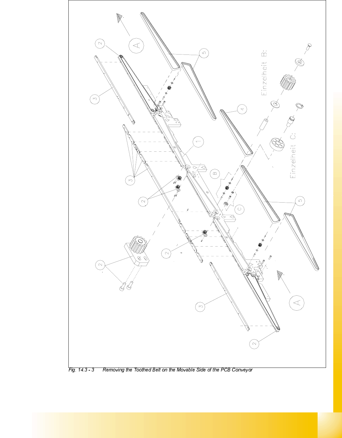
5HPRYLQJWKH7RRWKHG%HOWRQWKH0RYDEOH6LGHRIWKH&RQYH\RU
➠ Carry out DOOsteps as described for the removal of the conveyor belt for the fixed side in section
14.3.4.1but with the following differences:

07/2002 Edition Student Guide HS-50 Advanced II
14 Conveyor System
28
➠ Remove the faulty conveyor belt from the guide channel for the movable side.
➠ Lift the conveyor belt out over the drive unit which has been removed.
,QVWDOOLQJWKH7RRWKHG%HOWIRUWKH0RYDEOH6LGHRIWKH&RQYH\RU
CAUTION O
The new toothed belt must not be stretched or kinked. 14
➠ Carry out DOOsteps as described in section 14.3.4.2 for the installation of the conveyor belt for
the fixed side but with the following differences:
➠ Lift the new conveyor belt in over the conveyor drive unit which has been removed.
➠ Place the new toothed belt in the guide channel of the movable conveyor side -> The con-
veyor belt must be engaged over its entire width.
➠ Adjust the guide rails (see section 14.3.7).
➠ Carry out the pertinent )LQDOVWHSVLQFOXGLQJIXQFWLRQFKHFN(see section 14.4).
For the function check, transport a PCB from the input or preceding station to the output or fol-
lowing station.
Student Guide HS-50 Advanced II 07/2002 Edition
14 Conveyor System
29