HS50_advance_level 2.pdf - 第198页
07/2002 Editio n Student G uide HS -50 Advanc ed II 7 X-Axis 40 2YH UYLHZ PRGXODUKHDG ERDUG 2SWLRQIRU+ 6 (1) Video signal s PCB c amera (2) Vision Il luminati on PCB camera (3) Reference- / L imit switch …
Student Guide HS-50 Advanced II 07/2002 Edition
7 X-Axis
39
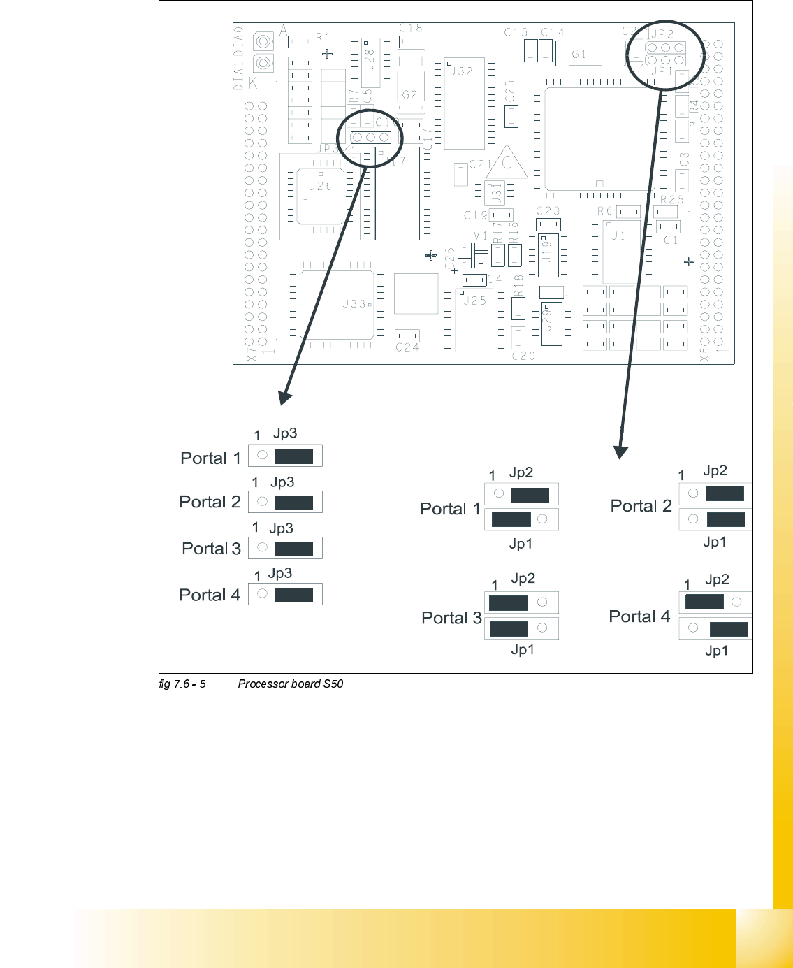
-XPSHU6HWWLQJV3URFHVVRU%RDUG6
R12
R19
R24
R20
R23
R22
R21
R12
C10
C9 R11
R10
R 9
R8
R15
R14
R13
C13
C12
C11
C13
C12
C11
07/2002 Edition Student Guide HS-50 Advanced II
7 X-Axis
40
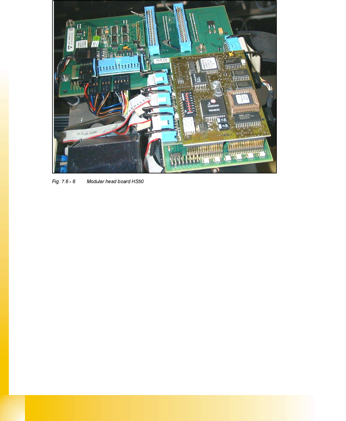
2YHUYLHZPRGXODUKHDGERDUG2SWLRQIRU+6
(1) Video signals PCB camera
(2) Vision Illumination PCB camera
(3) Reference- / Limit switch - Bero‘s
(4) Track signals for X-Axis
(5) Intermediate distributor board for C&P-head
(6) valve drive for placement/pick up position
(7) valve drive reject position
(8) Motor dp-station
(9) Setp motor dp-station
(10) Vacuum test board
(11) LED V9-V14
(12) DIP-Switch Portal 1-4 <=> Kopfplatine
(13) Vision component Camera
(14) 7 Segment display
3RLQW/('99
LZOS Light barrier Z-axis upper stop
LZUS Light barrier Z-axis down position
LSOI Light barrier IC Head top position (not used)
LSZD Light barrier Swivel in and turning dp-station
LSVZ Light barrier Vacuum / air blow Z-axis
LSVA Light barrier Vacuum / air blow reject position
Point 12: (see Section Fig. 7.6 - 7, Page - 41)
Point 14: ( see , page - 42)
Student Guide HS-50 Advanced II 07/2002 Edition
7 X-Axis
41
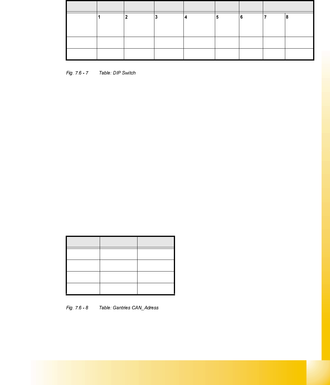
1HZ-XPSHU6HWWLQJRQWKHPRGXODUKHDGERDUG
Set the DIP switch on the processor board on the basis of the following data.
You will see the position of the switch in Fig. 7.6 - 8 , below.
7KHZLULQJRIWKHVZLWFKGHSHQGVRQWKHSODFHPHQWPDFKLQHLQYROYHG
Jumper 1: ON -> CAN matching resistor on the placement head is set
(S-20, F4, F5), S-23, 6+0, F5 HM.
OFF ->CAN_matching resistor is not wired on the head (+6 default)
Jumper 2: ON -> Setting during the download
OFF -> Default status
Jumper 3: ON -> Test mode
OFF -> Default status
Jumper 4: ON -> Test mode (setting of CAN ID)
OFF -> Default status
Jumper 5: ON -> Default status
Jumper 6: ON -> Default status
Jumper 7, 8: CAN_ID:
6WDQGDUG 2)) 2)) 2)) 2)) 21 21 &$1B$GUHVV
Position
of switch
CAN_R120 EPROM_WE Test_Mode CAN_ERR_
SWITCH
Jumper 5 Jumper 6 CAN_ID1 CAN_ID0
21 ; ;
2)) ; ; ; ;
*DQWULHV -XPSHU -XPSHU
Gantry 1 21 21
Gantry 2 21 2))
Gantry 3 2)) 21
Gantry 4 2)) 2))