HS50_advance_level 2.pdf - 第409页
Stud ent Gu ide HS-5 0 Adva nced II 07/2 002 Ed ition 14 Conve yor System 35 ([FKDQJ LQJWKH/LI WLQJ7 DEOH0RWRUD QGRUWKH6 SURF NHW: KHHO 5HPRY LQJW KH/LI WLQJ7 DEOH0RWRU 6 SURFN HW:KHH O …

07/2002 Edition Student Guide HS-50 Advanced II
14 Conveyor System
34
➠ Place the lifting table plate upside down on a clean, flat surface.
➠ Carry out the steps in the area under the lifting table plate (e.g., exchange the proximity switch
for the motor or the lifting table or the limit switch for min./max. conveyor width as described in
the pertinent section below.
,QVWDOOLQJWKH/LIWLQJ7DEOH
WARNING OO
During the subsequent installation of the lifting table plate there is a risk of body members being
pinched, crushed or cut off, e.g., between the outer edges of the lifting table plate and the con-
veyor assemblies. 14
➠ Make certain that the WUDQVPLVVLRQOHYHU on the pertinent lifting table motor is folded down on
the lifting curve (see Fig. 14.3.5, illustration bottom left).
➠ Holding the lifting table ZLWKERWKKDQGV, place itinto the guiding tubes with the guide pillars
YHUWLFDO (see ).
➠ Let the lifting table plate slowly side down.
➠ Check whether the lifting table plate is FRPSOHWHO\ seated on the lifting curve.
➠ Install the pertinent ball bearing on the rocking levers (see Fig. 14.3.4).
Student Guide HS-50 Advanced II 07/2002 Edition
14 Conveyor System
35
([FKDQJLQJWKH/LIWLQJ7DEOH0RWRUDQGRUWKH6SURFNHW:KHHO
5HPRYLQJWKH/LIWLQJ7DEOH0RWRU6SURFNHW:KHHO
➠ Remove the lifting table as described in section 14.3.8.1.
14
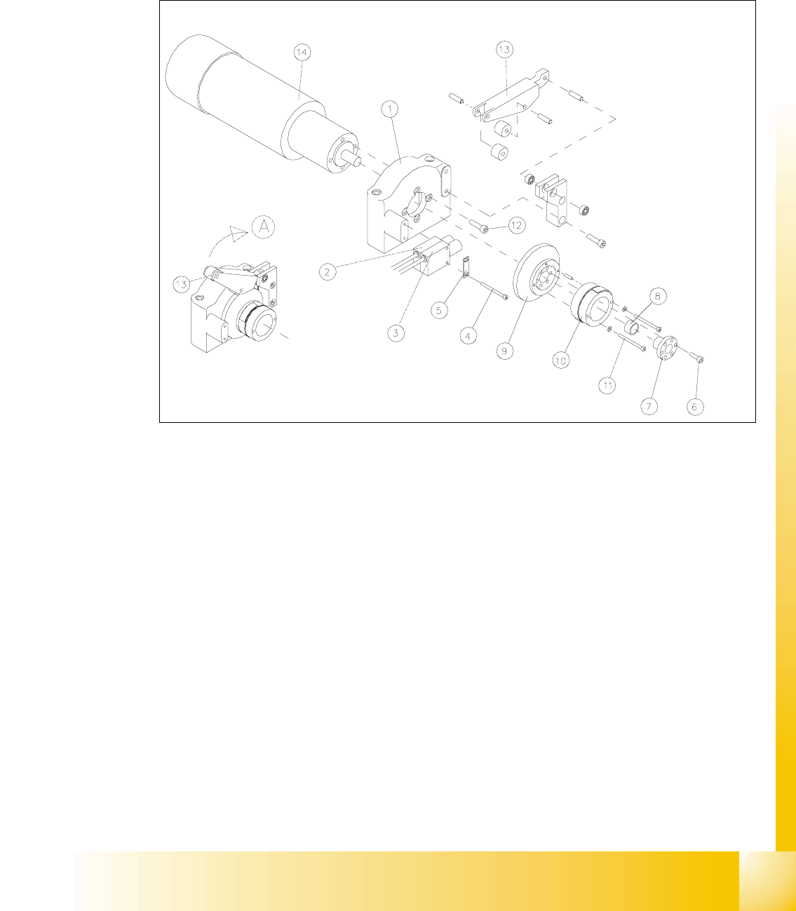
Fig. 14.3.5 Removing the LiftingTable Motor and / or the Lifting Table Proximity Switch
Key to Fig. 14.3.5
A) Fold the transmission lever XS
1) Motor mount 2) Proximity switch "lifting table GRZQ"
3) Proximity switch "lifting table XS 4) Screws fastening the proximity switch :
2 hexagonal socket head cap screws M3 x
30
5) Reinforcement plate for proximity switch 6) Fasteners for clamping flange:
6 hexagonal socket head cap screws
M4x12
7) Clamping flange 8) Annular spring
9) Cam body 10) Sprocket wheel with lead tapes
11) Screws fastening the "sprocket wheel with
lead tapes": 2 hexagonal socket head cap
screws M 3 x 30 with 2 adjusting shims
12) Motor moiunt: 4 hexagonal socket head
cap screws M5 x 12
13) Transmission lever 14) Motor for lifting table 1, 2, 3 or 4

07/2002 Edition Student Guide HS-50 Advanced II
14 Conveyor System
36
NOTE
The lifting table motors are prefitted with cable and connector (different article numbers, depend-
ing on placement area 1-4). 14
➠ Undo and remove the six M4 hexagonal socket head cap screws on the clamping flange (see
Fig. 14.3.5 -> 6). Remove the annular spring under the clamping flange.
➠ Label the allocation of the proximity switch for "lifting table up" and "lifting table down" (see Fig.
14.3.5).
➠ Remove the 2 proximity switches from the motor mount (two M3 hexagonal socket head cap
screws), see Fig. 14.3.5, and take off the "reinforcement plate for proximity switch" in the pro-
cess. Set the proximity switch down on the mounting plate.
➠ Fold XSthe transmission lever (see Fig. 14.3.5 -> 13) on the motor mount.
➠ Undo and remove the 2 hexagonal socket head cap screws on the sprocket wheel (see Fig.
14.3.5 -> 11).
Be careful with the washers underneath and remove the sprocket wheel incl. cam body.
➠ Lift off the cover of the pertinent cable duct which is parallel to the conveyor assembly.
➠ &DUHIXOO\remove the corresponding cable ties.
➠ In the cable duct, disconnect the plug-and-socket connection of the lifting table motor which is
to be removed (X70 / X71 / X72 / X73: see circuit diagram for 3RZHUVXSSO\IRUOLIWLQJWDEOH
PRWRUV.
NOTE:
If you discovered a break in the lifting table cable during a continuity test, the cable to the power
supply unit must be run on a weaving course and disconnected at the corresponding connector
X5 / X 6 / X7 / X8 (see above-mentioned circuit diagram).
You may wish to contact Siemens SMD Service regarding this work. 14
➠ Undo and remove the screws fastening the motor to the motor mount (four M5 hexagonal
socket head cap screws) and pull the lifting table motor out.
,QVWDOOLQJWKH/LIWLQJ7DEOH0RWRU6SURFNHW:KHHO
➠ Install the new lifting table motor and the (new) sprocket weel in the reverse order to that de-
scribed for the removal (see section 14.3.9.1).
The pin in the sprocket wheel secures the VSURFNHWZKHHOLQWKHFRUUHFWSRVLWLRQ.
CAUTION O
When several lifting table motors are being removed/installed at the same time, check that the
plug-and-socket connections in the cable duct are allocated correctly (see the circuit diagram
:Power supply for lifting table motors 1 - 4"). The strain on the plug-and-socket connections must
be relieved after the cable ties are attached. 14