HS50_advance_level 2.pdf - 第395页
Stud ent Gu ide HS-5 0 Adva nced II 07/2 002 Ed ition 14 Conve yor System 21 Key to A) PCB transpor t directi on B) Directi on in which d.c . geared motor is remov ed 1) Fixed conv eyor si de (pla cemen t area 1, 3 ; int…

07/2002 Edition Student Guide HS-50 Advanced II
14 Conveyor System
20
Conduct all the procedures for exchanging all d.c. geared motors as described below:
➠ )RUWKHGLVDVVHPEO\DW3&%FRQYH\RUGXDOFRQYH\RU
Move conveyor 1 RQO\IDUHQRXJKDSDUWthat the outside of the fixed conveyor assembly of
conveyor is still accessible so that the screws fastening the motor are also still accessible.
➠ )RUWKHGLVDVVHPEO\DWWKHVLQJOHFRQYH\RURUFRQYH\RURIWKHGXDOFRQYH\RU
Move the conveyor to PD[LPXPwidth.
➠ Move the Y-gantries into the area outside of the PCB conveyor.
➠ Turn off the machine at the main switch and disconnect the machine from the mains voltage.
➠ Conscientiously secure the machine against reactivation while servicing is in progress.
➠ Where applicable, undo and remove the screws fastening the sonar proximity switch mount to
the motor mount (two M3 hexagonal socket head cap screws) and set the mount and sensor
down without damaging the cables.
➠ Mark the polarity of the cable connections (+/ -) -> important for the direction of rotation!
➠ Disconnect the cable shoes from the motor terminals (see NOTE below).
➠ The heat-shrinkable sleeves which hold the connecting cable in place must be stripped off the
circumference of the d.c. geared motor.
➠ Dismantle the motor mount from the fixed side of the conveyor (two M4 hexagonal socket head
cap screws: see -> 4).
➠ Working from the fixed exterior side of the conveyor, undo the screws fastening the d.c. geared
motor in place (4 hexagonal socket head cap screws: see ).
➠ Tip the d.c. geared motor with the synchronized disk a little so that the small toothed belt of the
drive comes free of the synchronizing disk ( -> B) and pull the motor out.
Please note:
– The toothed belt on the motor pinion is not to be stretched or kinked during this pro-
cess.
– The synchronizing disk on the motor shaft must be moved out in such a manner that it does
not get hung up in the toothed belt.
NOTE:
If you have discovered a break in the motor cable due to a continuity check, the motor cable
must be run on a weaving course as far as the "&RQYH\RUFRQWURO3&%RU3&%(see cir-
cuit diagrams with the same name) and unplugged at the corresponding connector at the con-
veyor control.
This may be somewhat complicated depending on the routing of cables inside the machine base.
You may wish to contact Siemens SMD Service regarding this work. 14
Student Guide HS-50 Advanced II 07/2002 Edition
14 Conveyor System
21
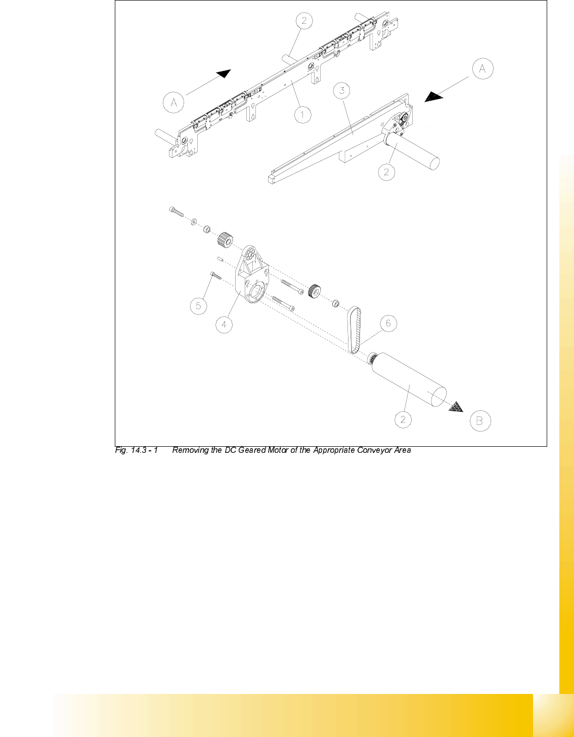
Key to
A) PCB transport direction B) Direction in which d.c. geared motor is
removed
1) Fixed conveyor side (placement area 1, 3;
intermediate conveyor; placement area 2,
4)
Set up at input in a like manner.
2) DC geared motor for conveyor belt drive
3) Fixed conveyor side of the output 4) Motor mount assembly, fastening:
Two hex. socket head cap screw M4 x 20
5) Fastening screws for DC geared motor:
Four hex. socket head cap screw M3 x 10
6) Toothed belt Synchroflex
(do not kink or stretch !)

07/2002 Edition Student Guide HS-50 Advanced II
14 Conveyor System
22
,QVWDOOLQJWKH*HDUHG0RWRURIWKH3&%&RQYH\RU'ULYH
CAUTION O
The toothed belt must not be stretched or kinked. 14
➠ Install the new d.c. geared motor in the reverse order to that described in section 14.3.1.1.
The HQWLUHZLGWK of the toothed belt must engage at the top and bottom synchronizing disk.
➠ Fasten the d.c. geared motor with the four M3 hexagonal socket head cap screws (see -> 5).
➠ Put the cable shoes on the motor terminals (+/-) in the correct polarity (direction of rotation!).
➠ Use the two heat-shrinkable sleeve rings to hold the cable to the circumference of the d.c.
geared motor.
➠ Install the sonar proximity switch mount (incl. sensor head) back on the motor mount (see ->
20).
➠ Perform the )LQDOVWHSVLQFOXGLQJIXQFWLRQFKHFN (see section 14.4).
NOTE:
After the gear motor has been installed, you must make certain that the direction of rotation and
the conveyor speed are correct (motor voltage). Proceed as stipulated in "Setting Instructions for
HS-50". 14
5HSODFLQJWKH7RRWKHG%HOWRIWKH3&%&RQYH\RU'ULYH
The following instructions apply for all 5 conveyor areas of conveyors 1 and 2. 14
NOTE
For this work the sonar proximity switch mount incl. sensor on the input and intermediate conveyor
must be removed and subsequently re-installed. During this process, the connecting cables are
not to be kinked or bent sharply. Carefully set the mount incl. sonar proximity switch down on the
machine base. 14
5HPRYDO7RRWKHG%HOWIRU3&%&RQYH\RU'ULYH
➠ For the removal from PCB conveyor 1, when dual conveyor involved:
Move the conveyor 1 only so far apart that the exterior of the movable conveyor assembly is
still sufficiently accessible to loosen the screws fastening the end shield (see -> 5).
➠ )RUWKHUHPRYDOIURPWKHVLQJOHFRQYH\RU Move the conveyor to PD[LPXPwidth.
➠ Move the Y-gantries into the area outside the PCB conveyor.
➠ Turn off the machine at the main switch and disconnect the machine from the mains.
➠ Conscientiously secure the machine against being turned back on during the servicing.