HS50_advance_level 2.pdf - 第397页
Stud ent Gu ide HS-5 0 Adva nced II 07/2 002 Ed ition 14 Conve yor System 23 Key to A) Layo ut on th e mova ble side of the conveyo r -XVW un do the s crews fastening the end shie ld ! B) Layo ut on the fixed s ide of t…

07/2002 Edition Student Guide HS-50 Advanced II
14 Conveyor System
22
,QVWDOOLQJWKH*HDUHG0RWRURIWKH3&%&RQYH\RU'ULYH
CAUTION O
The toothed belt must not be stretched or kinked. 14
➠ Install the new d.c. geared motor in the reverse order to that described in section 14.3.1.1.
The HQWLUHZLGWK of the toothed belt must engage at the top and bottom synchronizing disk.
➠ Fasten the d.c. geared motor with the four M3 hexagonal socket head cap screws (see -> 5).
➠ Put the cable shoes on the motor terminals (+/-) in the correct polarity (direction of rotation!).
➠ Use the two heat-shrinkable sleeve rings to hold the cable to the circumference of the d.c.
geared motor.
➠ Install the sonar proximity switch mount (incl. sensor head) back on the motor mount (see ->
20).
➠ Perform the )LQDOVWHSVLQFOXGLQJIXQFWLRQFKHFN (see section 14.4).
NOTE:
After the gear motor has been installed, you must make certain that the direction of rotation and
the conveyor speed are correct (motor voltage). Proceed as stipulated in "Setting Instructions for
HS-50". 14
5HSODFLQJWKH7RRWKHG%HOWRIWKH3&%&RQYH\RU'ULYH
The following instructions apply for all 5 conveyor areas of conveyors 1 and 2. 14
NOTE
For this work the sonar proximity switch mount incl. sensor on the input and intermediate conveyor
must be removed and subsequently re-installed. During this process, the connecting cables are
not to be kinked or bent sharply. Carefully set the mount incl. sonar proximity switch down on the
machine base. 14
5HPRYDO7RRWKHG%HOWIRU3&%&RQYH\RU'ULYH
➠ For the removal from PCB conveyor 1, when dual conveyor involved:
Move the conveyor 1 only so far apart that the exterior of the movable conveyor assembly is
still sufficiently accessible to loosen the screws fastening the end shield (see -> 5).
➠ )RUWKHUHPRYDOIURPWKHVLQJOHFRQYH\RU Move the conveyor to PD[LPXPwidth.
➠ Move the Y-gantries into the area outside the PCB conveyor.
➠ Turn off the machine at the main switch and disconnect the machine from the mains.
➠ Conscientiously secure the machine against being turned back on during the servicing.
Student Guide HS-50 Advanced II 07/2002 Edition
14 Conveyor System
23
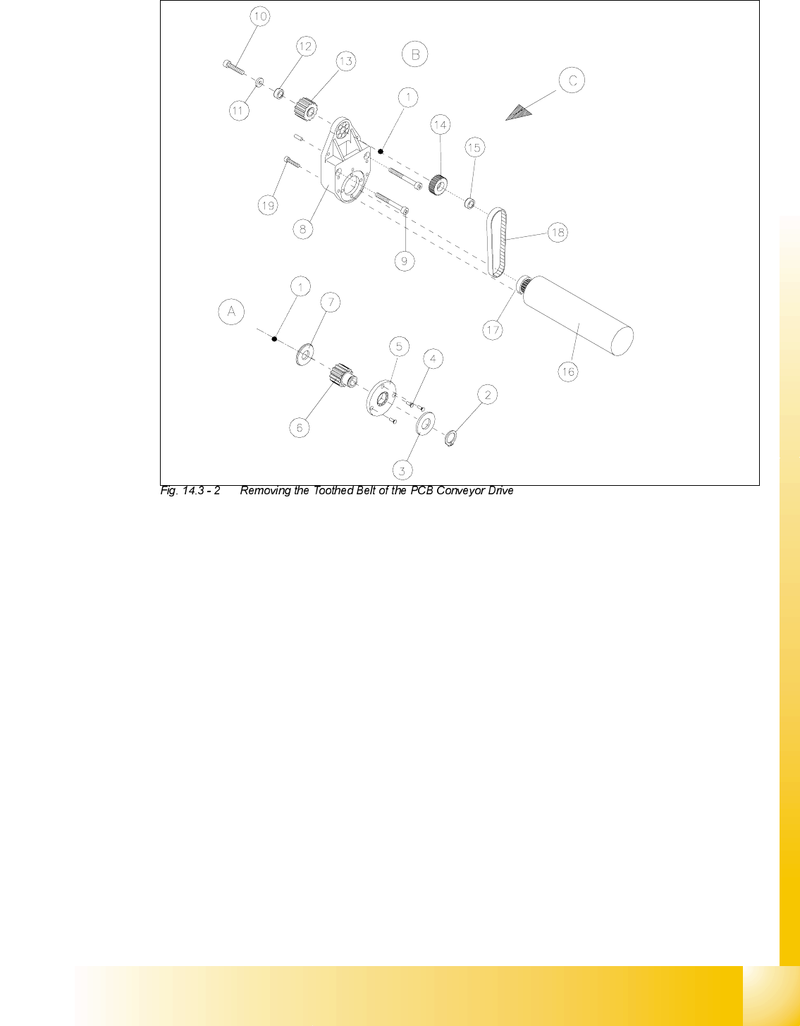
Key to
A) Layout on the movable side of the conveyor
-XVWundo the screws fastening the end
shield !
B) Layout on the fixed side of the conveyor
C) PCB transport direction
1) Hexagonal drive shaft 2) Retaining ring (is not removed)
3) Disk (is not removed) 4) 3 slotted screws M2 x 5
5) End shield 6) Synchronizing disk
7) Disk 8) Motor mount assembly
9) Screws fastening the motor mount: parallel
pin, 2 hex socket head cap screws M4 x
20,
10) Screw fastening the drive shaft:
hexagonal socket head cap screw M4 x 10
11) Pressure disk 12) Annular spring
13) Synchronizing disk (toothed belt for conv.) 14) Synchronizing disk (toothed belt for drive)
15) Annular spring (Tension element) 16) DC geared motor
17) Synchronizing disk 18) Toothed belt Synchroflex 6 T2.5/177.5
19) Screws to fasten geared motor
4 hex socket head cap screws M3 x 10

07/2002 Edition Student Guide HS-50 Advanced II
14 Conveyor System
24
➠ 5HOLHYHWKHWHQVLRQon the relevant pair of toothed belts by loosening the fasteners of the al-
located EHOWJXLGH on the fixed DQGmovable side of the conveyor (two M3 hexagonal socket
head cap screws each: see!).
➠ When exchanging at the LQWHUPHGLDWHRULQSXWFRQYH\RU
Where applicable, disassemble the sonar proximity switch mount incl. the sensing head ->
Keep the above NOTE in mind.
➠ Mark the polarity of the motor terminals (+/-) -> Important for restoring the direction of rotation.
➠ Pull the cable shoes off the motor terminals.
➠ Pull the heat-shrinkable sleeves (which hold the cable in place) off the motor.
➠ For the exchange at conveyor 1 or 2:
➠ On the movable side of conveyor 1 or 2 undo the screws fastening the end shield ((3 slotted
M2 screws: see -> 5).
➠ If a dual conveyor is present (and the toothed belt on conveyor 1 is exchanged) also
loosen the screws fastening the end shield at conveyor 2.
➠ $WWKHIL[HGVLGHRIWKHFRQYH\RU
➠ Undo and remove the screws fastening the pertinent motor mound (two M 4 hexagonal
socket head cap screws: see ).
➠ In case involving both a dual converter and exchanging the toothed belt at conveyor 1, the
screws fastening the motor mount must be undone (see -> 4). This creates space to re-
move the end shield, moving in the direction of conveyor 2.
➠ On the drive unit, remove the pressure disk, the annular spring (tensioning element) and
the synchronizing disk from the hexagonal drive shaft.
➠ Push the drive unit toward the movable side of the conveyor until the synchronizing disk of
the drive no longer engages in the toothed belt of the conveyor.
Where a dual conveyor is present (and the toothed belt on conveyor 1 exchanged), first
push the drive shaft of conveyor 2 away from conveyor 1 to make room for the drive shaft
of conveyor 1. Then push the drive shaft of conveyor 1 away too.
➠ Remove the damaged toothed belt for the drive from the motor mount.
,QVWDOOLQJWKH7RRWKHG%HOWIRUWKH3&%&RQYH\RU'ULYH
CAUTION O
The new toothed belt is not to be stretched or kinked during the following procedure. 14
➠ Insert the new toothed belt into the relief cut in the motor casing (see ).
➠ Place the toothed belt around the synchronizing disk of the geared motor.
➠ In the opening of the motor mount, pull the toothed belt up slightly but do not stretch it.
➠ Guide the hexagonal drive shaft with synchronizing disk (see ) into the motor mount.