HS50_advance_level 2.pdf - 第148页
07/2002 Editio n Student G uide HS -50 Advanc ed II 6 Cont rol & C ommun icatio n 18 )XQFWLRQLQ JRIWKH $ [HV%RDUGV $ [LV 6HUYR&DUG3ULQFLSOH V Basic axi s card fun ction The axis b oards c o…
Student Guide HS-50 Advanced II 07/2002 Edition
6 Control & Communication
17
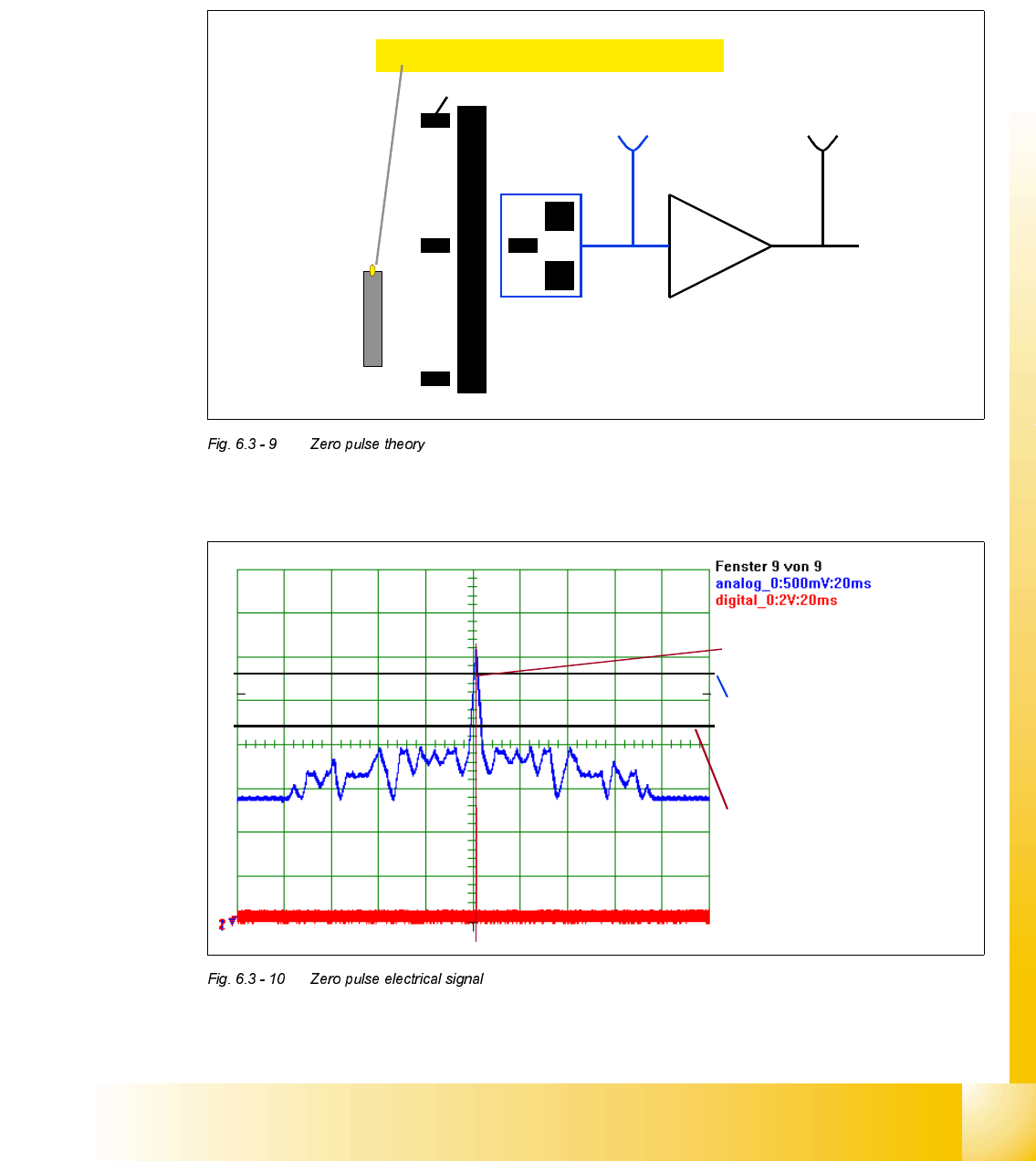
=HUR3XOVH7KHRU\
The Zero pulse of the axes is a singular signal in the whole travel range. This defines the “home
position” where position counting starts. On the X & Y axes the Zero pulse is repeated within the
travel range, however only one signal is used. During the reference run this zero pulse window is
detected with help of proximity switches (Bero).
=HURSXOVHHOHFWULFDOVLJQDOVHHQRQDQRVFLOORVFRSH
Zero pulse window (repeated)
Proximity switch (Bero)
At 2,7 V the Schmitt Trigger-
circuit generates the digital
Zero pulse signal.
The analogue Zero pulse
should override this threshold.
Interference pulses should not
override this limit.
07/2002 Edition Student Guide HS-50 Advanced II
6 Control & Communication
18
)XQFWLRQLQJRIWKH$[HV%RDUGV
$[LV6HUYR&DUG3ULQFLSOHV
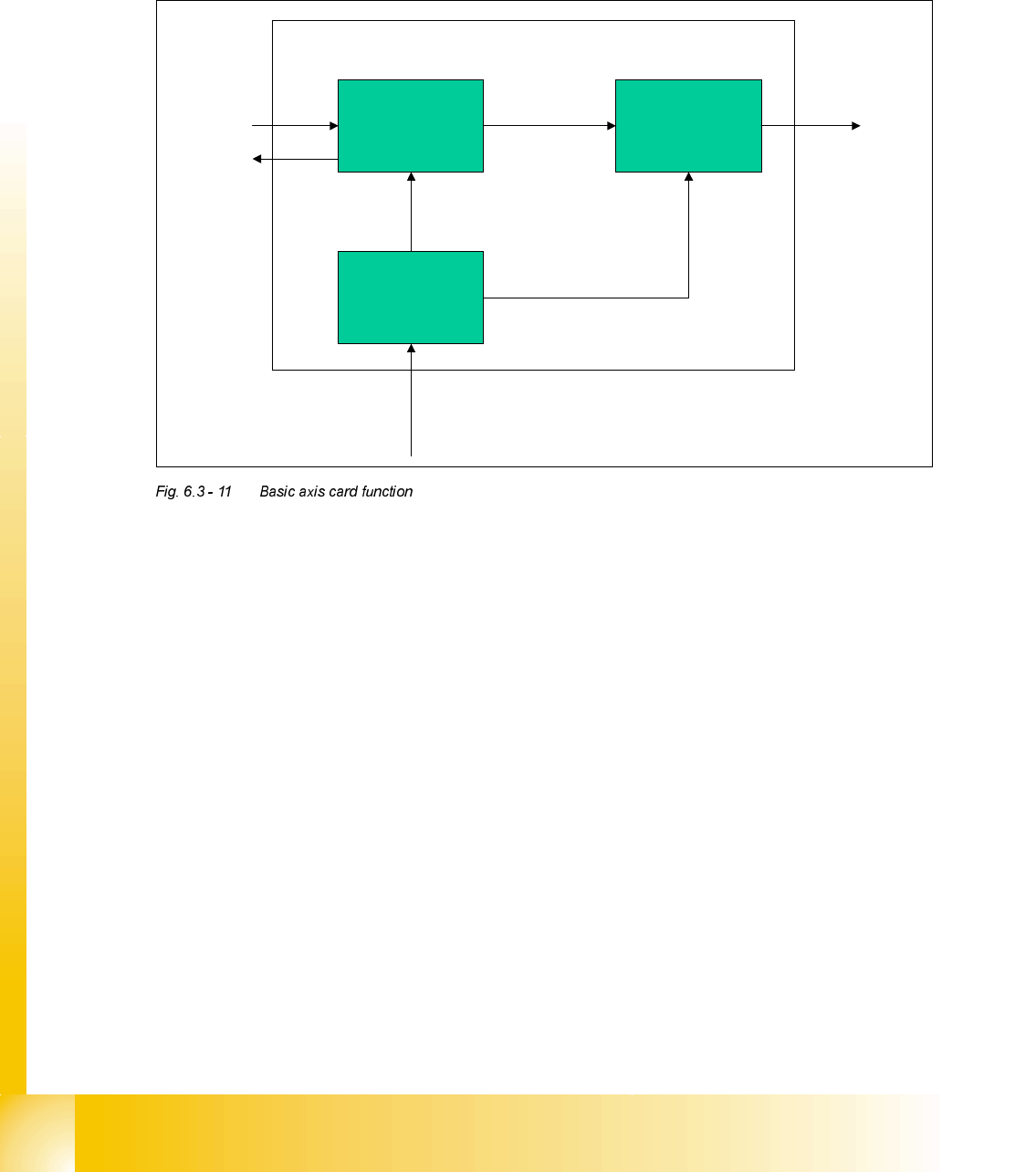
Basic axis card function
The axis boards control the movement of the axes. The axis controller receives commands and
the necessary parameters via SMP bus connection from the MC. In the same way an end signal
is returned to the MC. The axis controller outputs a direct voltage to the speed controller in the
servo amplifier (V nom). The voltage level and the polarity here determine the speed of movement
and the direction.
An additional voltage (force) is supplied to the servo amplifier which is used to set the force limit
during Z-axis movement. Also with this output we generate another signal to speed up the accel-
eration and deceleration phase of X and Y (S2x) axis movement.
The current position of the axis is determined by means of the incremental path / angle measure-
ment system (track signals).
7KHD[LVFRQWUROOHUFRQVLVWVRIDSRVLWLRQDQGVSHHGGHWHFWLRQV\VWHP
This system uses the track signals produced by the encoder system. Within the system the posi-
tion counter is used to detect the current position. An overshoot counter is used during the final
positioning of the axis to monitor any overshoot passed the target position.
There is a speed detection system on the axis controller to prevent the axis from a crash situation
because of too high an axis speed. (info see error message "axis tachointerrupt")
Position Control
System
Speed Control
System (not for
Z axis)
Position and speed
detection system
Control signals
to & from
machine
controller
via SMP BUS.
Track signals from encoder system
Analogue
Signals to Servo
Card
( V nom + force
)
Student Guide HS-50 Advanced II 07/2002 Edition
6 Control & Communication
19
3RVLWLRQFRQWUROV\VWHP
This system consists of the following. The ’mailbox’ is used to store the position of the axis re-
quired by the machine controller (the ’Target’ position). The ’Target’ position and the actual posi-
tion, given by the position detection system, are supplied to a comparator, which compares the 2
inputs. The result is supplied to the ’Position Controller’, which outputs the required parameters
for the axis movement.
6SHHG&RQWUROV\VWHPIRUDGGLWLRQDOVSHHGXSGXULQJDFFHOHUDWLRQGHFHOHUDWLRQ
This system takes the output from the ’Position Controller’ and the input from the speed detection
system and compares them. This results in a speed requirement, which is fed to the servo card.
The digital signals are converted into an analogue output by a DAC. There are actually 2 outputs,
firstly the V nom, which directly controls the speed and direction of the movement. Secondly there
is the force output, which is used for the initial acceleration of the X & Y axis on S2x machines.
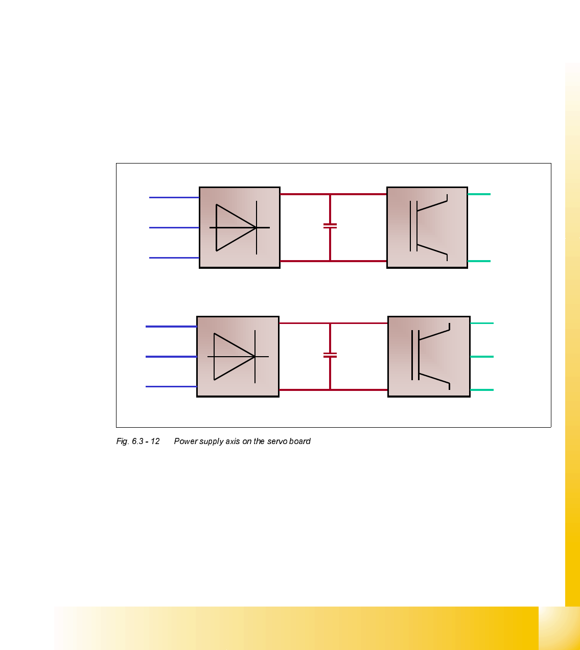
3RZHU6XSSO\$[LVRQWKH6HUYR%RDUG
With a rectifier we generate an appropriate constant DC-Voltage for the power semiconductor of
the axis servo amplifier. The power semiconductor on the DC servo board varies the DC-voltage
according to the speed the motor should move. If the motor should reverse the polarity is changed.
The power semiconductor on the AC servo board sets the voltage so that a sinusoidal motor cur-
rent moves the AC-motor. If the motor should speed up the frequency is increased. If the motor
should reverse the phase sequence is changed.
Power supply DC Axes
+
+ / -
AC from
Transformer
Constant DC
Motor DC
current
accordin
g
turning direction
AC from
Transformer
Constant DC
Sinusoidal
motor curren
t
+
Power supply 3 phase AC axis