HS50_advance_level 2.pdf - 第365页
S tudent Guide HS-50 Adva nced II Editio n 07/200 2 12 S pecial handlin g for th e Z-axis 21 'HVFULSWLR Q%ODVWDLU FRQWUR O Blast ai r contr ol at pla cemen t: V alue “0” mea n the bl ast air valve d on‘…

Student Guide HS-50 Advanced II
12 Special handling for the Z-axis Edition 07/2002
20
%ULHIGHVFULSWLRQRIWKHKDQGOLQJGDWDIRUWKHSODFHPHQWRSHUDWLRQ
3ODFLQJIRUFH
Force, measured via the current draw, with which the component is pressed into the soldering
paste. The value for the placing force is only active for certain Z-axis travel profiles.
%ODVWDLUISODFHPHQW
Here can be specified the starting point for switching off the blast air when placing a component,
as a result the blast pressure on the nozzel is influenced.(see 6.4.3 Blast air control)
%ODVWDLUIUHWXUQ
Here can be specified the starting point for switching off the blast air when returning a component
(MTC), as a result the blast pressure on the nozzel is influenced.(see 6.4.3 Blast air control)
:DLWLQJWLPH
The wait time is the time that the Z-axis waits on the surface of the component when placing the
component in order to ensure safe and accurate placement when travel profile modes are used
for the Z-axis.
9DFXXPFKHFNSULRUWRSODFHPHQW
A check is conducted on the vacuum before placing a component. The vacuum check is
automatically deactivated for 0201 placement and when nozzles of type 906/706 are used.
7UDYHOSURILOH
Different travel profiles can be selected for the up and down motion of the Z-axis.
Student Guide HS-50 Advanced II
Edition 07/2002 12 Special handling for the Z-axis
21
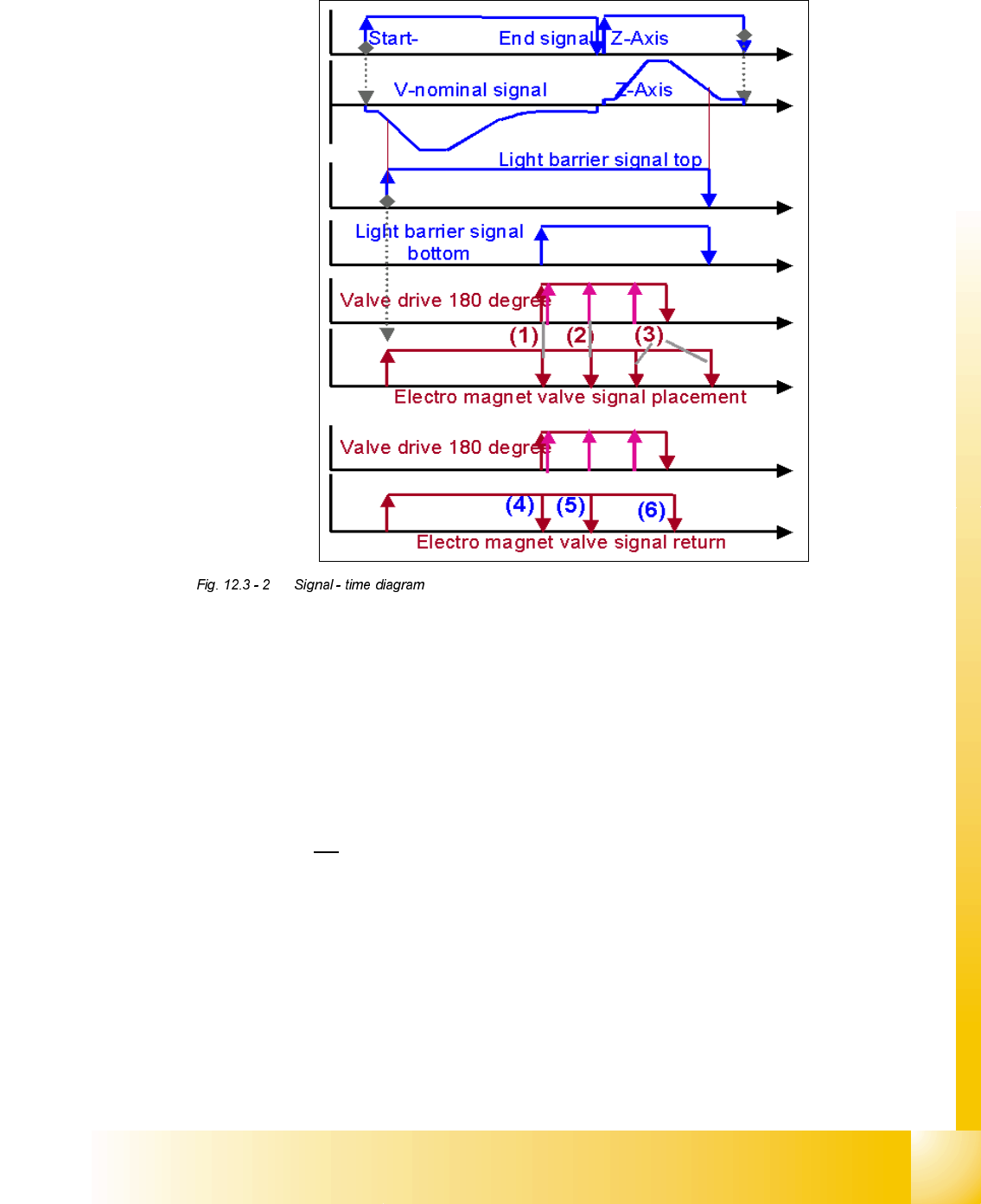
'HVFULSWLRQ%ODVWDLUFRQWURO
Blast air control at placement:
Value “0” mean the blast air valve don‘t switch on.
Value “1-50” mean blast air valve is switched OFF when stepper motor valve drive start to
move.
Value “51-150” mean blast air valve is switched OFF when stepper motor valve drive moved
for 90 degree.
Value. “151-255 mean blast air valve is switched OFF when stepper motor valve drive moved
for 180 degree.2U
at light barrier top.
No value “----” (from converting 501/502 to 503 format) mean same mode than (existing
standard).
Air kiss control at return component! (not reject)
Value and description like
Value and description like
Value. “151-255” mean blast air valve is switched OFF when stepper motor valve drive moved
for 180 degree.

Student Guide HS-50 Advanced II
12 Special handling for the Z-axis Edition 07/2002
22
7UDYHOSURILOHVRIWKH=D[LVZKHQSODFLQJFRPSRQHQWV
On the line computers the travel profile for the up and down motion of the Z-axis can be specified
for the placement operation for each package form.
1RWH
The travel profile specification also includes the special handling for packs of 8 nozzles, i.e. there
is no differentiation between nozzle types anymore on the MC.
=D[LVWUDYHOSURILOHGRZQZDUGVRQSODFHPHQW
0RGHNormal downward motion with light barrier at bottom
0RGHCreep mode and light barrier at bottom.
The Z-axis moves about 1mm before reaching the target position with V
min
and the forced air is
activated when switching the light barrier at the bottom.
0RGHCurrent sensor
The Z-axis moves with the current sensor pointed down, i.e. the Z-axis presses the component
into the soldering paste with the placing force defined.
0RGHCurrent sensor with creep
The Z-axis moves with the current sensor pointed down, and the system switches to V
min
1 mm
before reaching the target position, and the component is pressed into the soldering paste with
the specified placement force.
=D[LVWUDYHOSURILOHXSZDUGVRQSODFHPHQW
0RGHStandard mode
0RGHCreep mode, i.e. the Z-axis moves up slowly the first few millimeters.