HS50_advance_level 2.pdf - 第209页
Stud ent Gu ide HS-5 0 Adva nced II 07/2 002 Ed ition 7 X- Axis 51 'LJLW DO7 UDFN6LJQD OVRI*DQWU\$ [HV 0HDVXUHPHQWRI GLJLWDO 7UDF N6LJQDO VRI;$[HV&RQQHFWRU ;RQ+HDG %RDUG& .(&…
07/2002 Edition Student Guide HS-50 Advanced II
7 X-Axis
50
NOTE
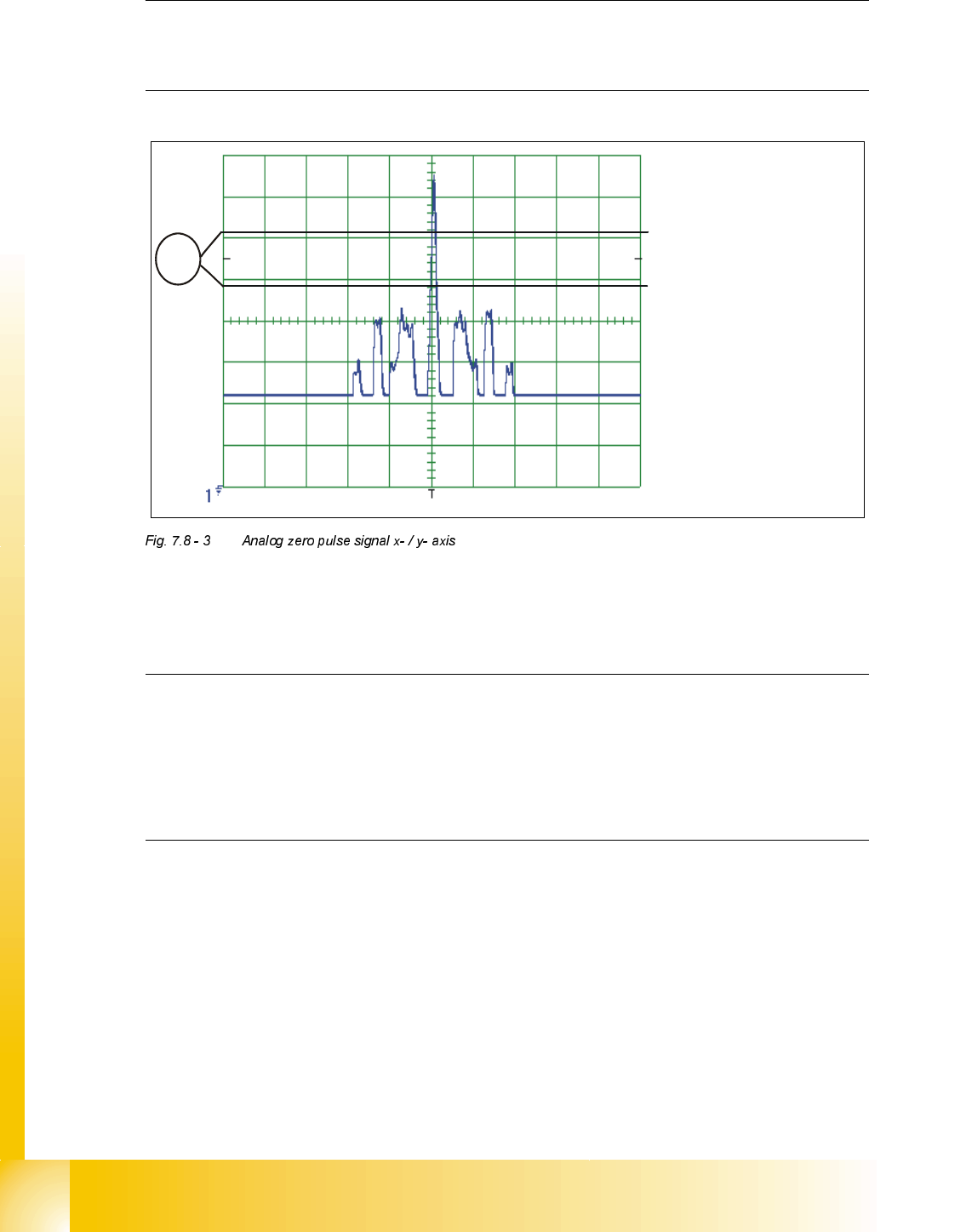
If you adjusted the read head correctly, the following illustration will appear on the screen of the
oscilloscope:
.(<
(1) No spurious peaks are allowed in this measuring range.
NOTE
Check the analog signal of the zero pulse, to ascertain that the zero pulse is discerned correctly.
If the zero pulse is not discerned correctly, the axis will reference to a spurious peak.
Placement offsets will be the result.
The pulse width of the analog zero pulse is dependent on the speed at which the axis is
traversed.
CH1
Student Guide HS-50 Advanced II 07/2002 Edition
7 X-Axis
51
'LJLWDO7UDFN6LJQDOVRI*DQWU\$[HV
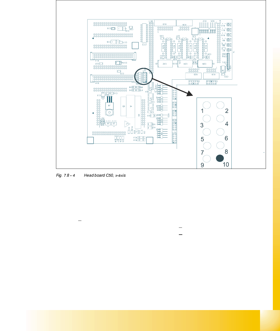
0HDVXUHPHQWRIGLJLWDO7UDFN6LJQDOVRI;$[HV&RQQHFWRU;RQ+HDG%RDUG&
.(<
; = x-axis
Pin configuration
;
1. Ground 2. Track A
3. Track A
4. Ground
5. Track B 6. Track B
7. Track N 8. Track N
9. -4V 10.removed
07/2002 Edition Student Guide HS-50 Advanced II
7 X-Axis
52
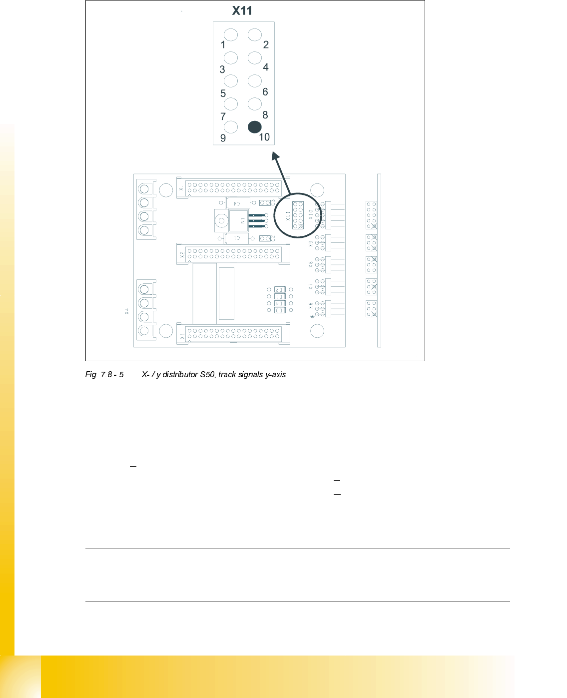
0HDVXULQJGLJLWDO7UDFN6LJQDOVRIWKH<$[HV&RQQHFWRU;RQ;<'LVWULEXWRU6
.(<
; = y-axis
Pin configuration:
NOTE
For troubleshooting you can use the pin on the head board/distributer board for measurement the
digital track signals.
1. Ground 2. Track A
3. Track A
4. Ground
5. Track B 6. Track B
7. Track N 8. Track N
9. -4V 10.removed