HS50_advance_level 2.pdf - 第166页
07/2002 Editio n Student G uide HS -50 Advanc ed II 7 X-Axis 8 The gant ry is fi xed t o the two sh uttles (s ee ite m 1 in F ig. 7.2 - 3 ) o f the reci rcul atin g bal l scr ew un it (se e it em 2 in Fig. 7.2 - 3 ) us…
Student Guide HS-50 Advanced II 07/2002 Edition
7 X-Axis
7
6WUXFWXUHRIWKHJDQWU\
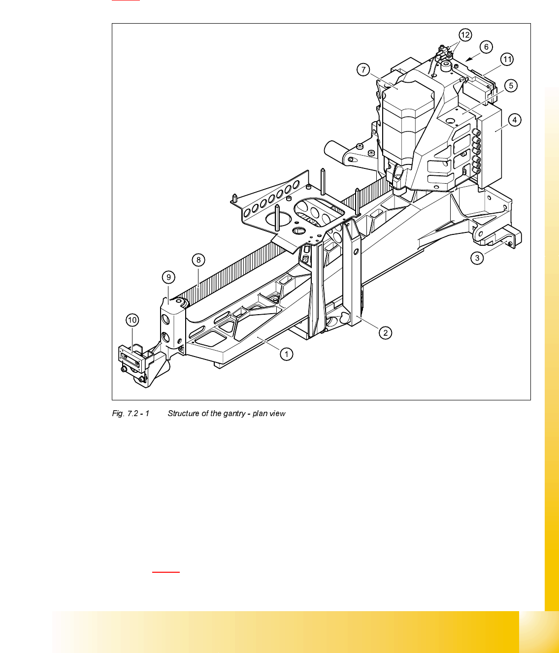
The principal element of the gantry is the torsionally rigid precision-cast gantry. Diagram
7.2 - 1
contains a plan view of its major components.
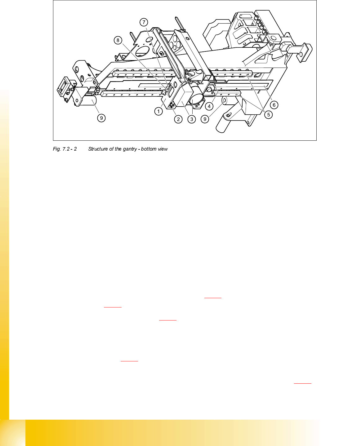
Diagram 7.2 - 2 shows a bottom view of the gantry.
(1) Precision-cast gantry (2) Head mount
(3) Incremental encoder for Y-axis scale (4) Primary part of the y linear motor
(5) Motor bracket (6) Thrust bearing
(7) X-axis motor unit (8) Toothed belt
(9) Deflection unit (10) Y-axis brake, external
(11) Y-axis brake, internal (12) Proximity switches B1 and B2 for the Y-axis
07/2002 Edition Student Guide HS-50 Advanced II
7 X-Axis
8
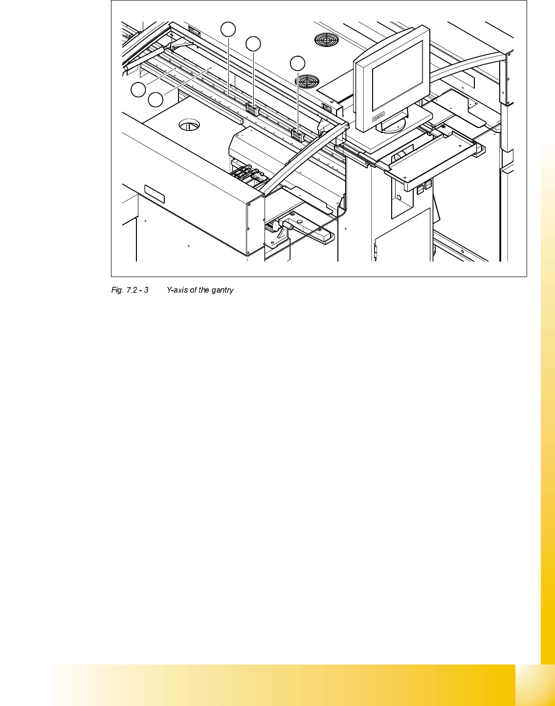
The gantry is fixed to the two shuttles (see item 1 in Fig. 7.2 - 3) of the recirculating ball screw unit
(see item 2 in Fig. 7.2 - 3
) using four M6 x10 hexagon socket-head screws.
The secondary part (see item 3 in Fig. 7.2 - 3
) of the Y-axis linear drive, with its permanent mag-
nets, is located above the guide rail of the recirculating ball screw unit. The secondary part is
mounted on the machine frame.
The air and power supply and signal lines for the gantry and collect&place head all run in a trailing
cable (see item 1 in Fig. 7.2 - 4
).
The seven power cables take the form of flexible ribbon cables, four of which are needed for the
collect&place head. They run beneath the cover in the machine frame (see item 1 in Fig. 7.2 - 5
),
between the head board on the head mount and the gantry board.
(1) Head mount
(2) X-axis brake
(3) PCB camera with lens system
(4) Incremental encoder for the X-axis
(5) Recirculating ball screw unit KUME 12B
(6) Scale for the X-axis
(7) End position proximity switch 2
(8) End position proximity switch 1 and reference point for the X-axis
(9) Elastomeric spring 25x10.5x50
Student Guide HS-50 Advanced II 07/2002 Edition
7 X-Axis
9
(1) Shuttles of the recirculating ball screw unit for the Y-axis
(2) Guide rail of the recirculating ball screw unit for the Y-axis
(3) Secondary part of the linear drive for the Y-axis (permanent magnets)
(4) Scale for the Y-axis
4
3
1
1
2