HS50_advance_level 2.pdf - 第352页
S tudent Guide HS-50 Ad vanced II 12 S pecial handlin g for th e Z-axis Edition 0 7/2002 8 (DUO\YDFXXP This funct ion s witches t he vacuu m on after exi ting fro m the upper light ba rrier to e nsure th at the best …
Student Guide HS-50 Advanced II
Edition 07/2002 12 Special handling for the Z-axis
7
%ULHIGHVFULSWLRQRIWKHKDQGOLQJGDWDIRUWKHSLFNXSRSHUDWLRQ
3ODFLQJIRUFH
This is the placement force applied to the component when picking up a component from the
feeder and is measured using the motor current. (Not active, the placement force must be
minimal).
:37&DFFHOHUDWLRQLQ\]
The acceleration for the corresponding axis can be reduced for y (MTC feed axis) and z (MTC
lifting axis).
:DLWLQJWLPH
The time that the Z-axis waits when picking up the component from the component surface in
order to guarantee 100% safety when picking up critical and possibly expensive components.
)HHGHUSLWFK
The distance between 2 components on the tape. This value is required along with traceability and
the splice detector to calculate the fill level to determine when a new component reel is needed.
&DXWLRQ
The entry for the feeder pitch value has priority 2 in the package form editor!!! The traceability
option assigns the entry for the feeder pitch value priority 1 in the component editor.
9DFXXPFKHFNGXULQJSLFNXS
A check is conducted on the vacuum after picking up a component. The vacuum check is
automatically deactivated for 0201 placement and when nozzles of type 906/706 are used.
$XWSLFNXSFRUUHFWLRQ
The pick-up position correction from the feeder is automatically calculated from the component
position of the nozzle.
1RWH
In previous software versions the automatic pickup correction was enabled and disabled with the
"Cubic Component" radio button. The "Cubic Component" radio button now manipulates just the
image scale for the Vision system.
Student Guide HS-50 Advanced II
12 Special handling for the Z-axis Edition 07/2002
8
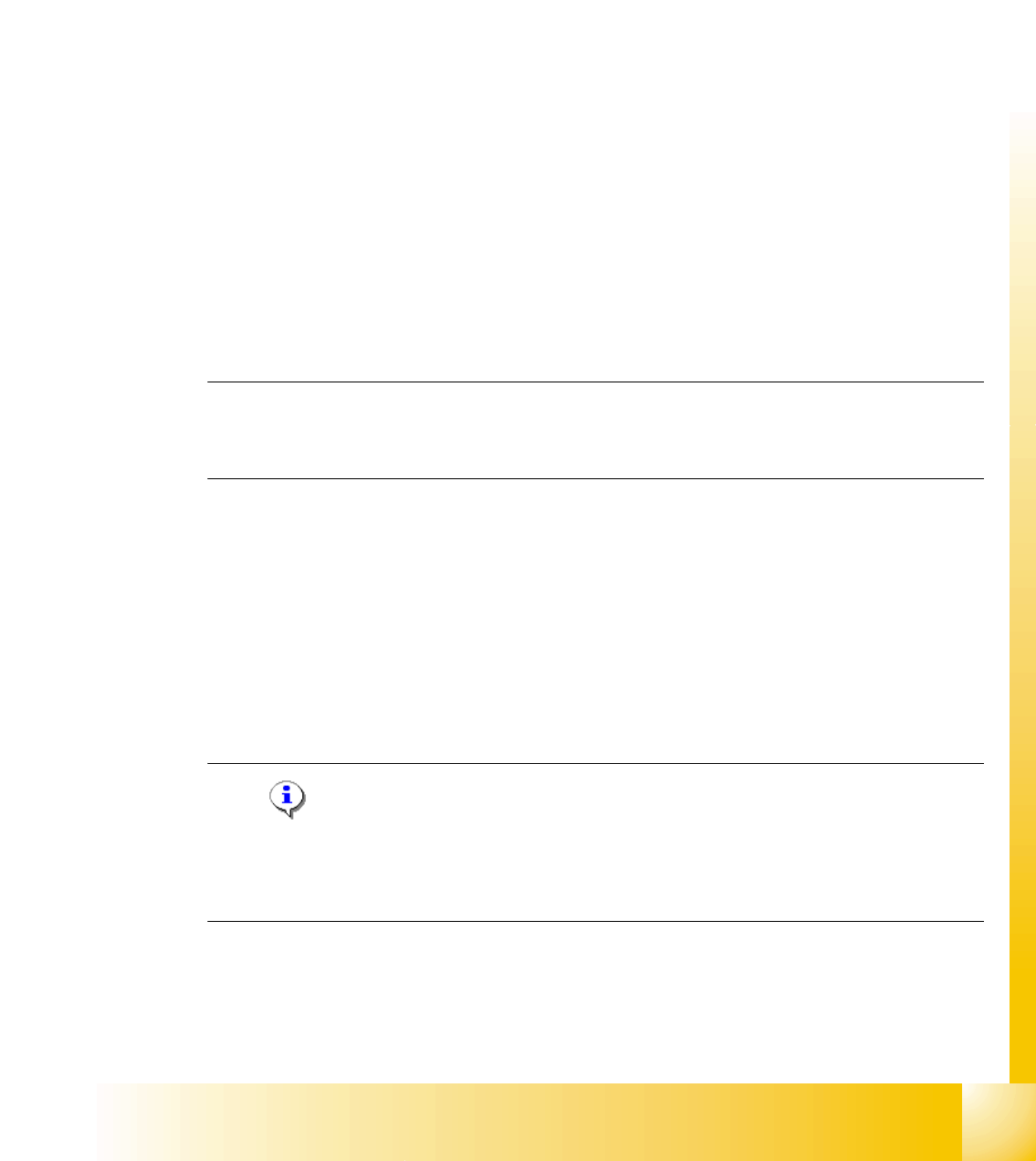
(DUO\YDFXXP
This function switches the vacuum on after exiting from the upper light barrier to ensure that the
best vacuum possible has been created in the nozzle.
3RZHUXSWLPHIRUWKHYDFXXP
The following power-up times for the vacuum can be defined individually for each package form:
1. Vacuum with light barrier: The vacuum is switched on just like before when "Light barrier at
bottom" is enabled. This corresponds to the Z-axis travel profile downwards mode 1.
2. Early vacuum: When the "Early vacuum" function is activated, the vacuum is switched on when
exiting from the upper light barrier.
3. MC switches on vacuum: The vacuum is switched on by the MC by the "Pick-up without
contact" function once the Z position has been reached.
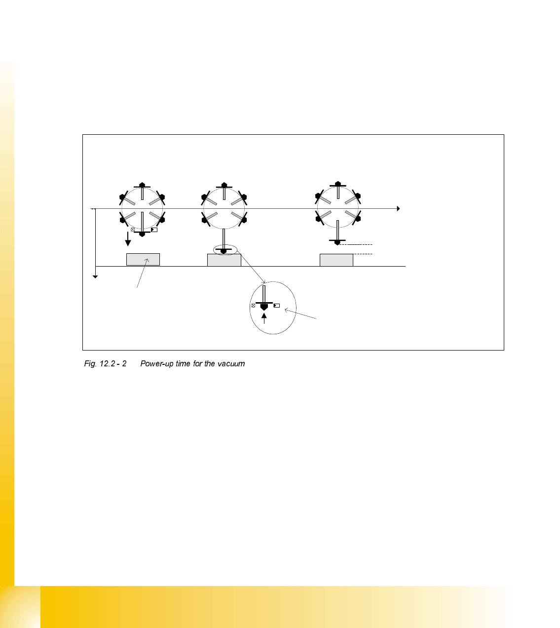
3LFNXSZLWKRXWFRQWDFW
Pick-up without contact was specially implemented for 0201-type components to minimize pick-
up errors.
Components (of type 0201, for example) can be picked up without making contact. The nozzle is
positioned a specific distance ("height clearance") over the component to do this. The component
is then drawn up to the nozzle with the help of the vacuum created (and switched on by the MC).
The height clearance (distance between the component and the nozzle) is stored in the machine
database. The same height clearance applies to all components for contact-free pick-up.
Early vacuum:
Z-axis head, upper light
barrier is activated
Vacuum:
Lower light barrier is
activated
Vacuum MC:
Z-axis has reached bottom position ->
MC issues the command to switch on the
vacuum
Height clearance
t
Pick-up at height
clearance level
Pick-up
z
Light
barrier
at top
Light barrier at bottom
Component
Student Guide HS-50 Advanced II
Edition 07/2002 12 Special handling for the Z-axis
9
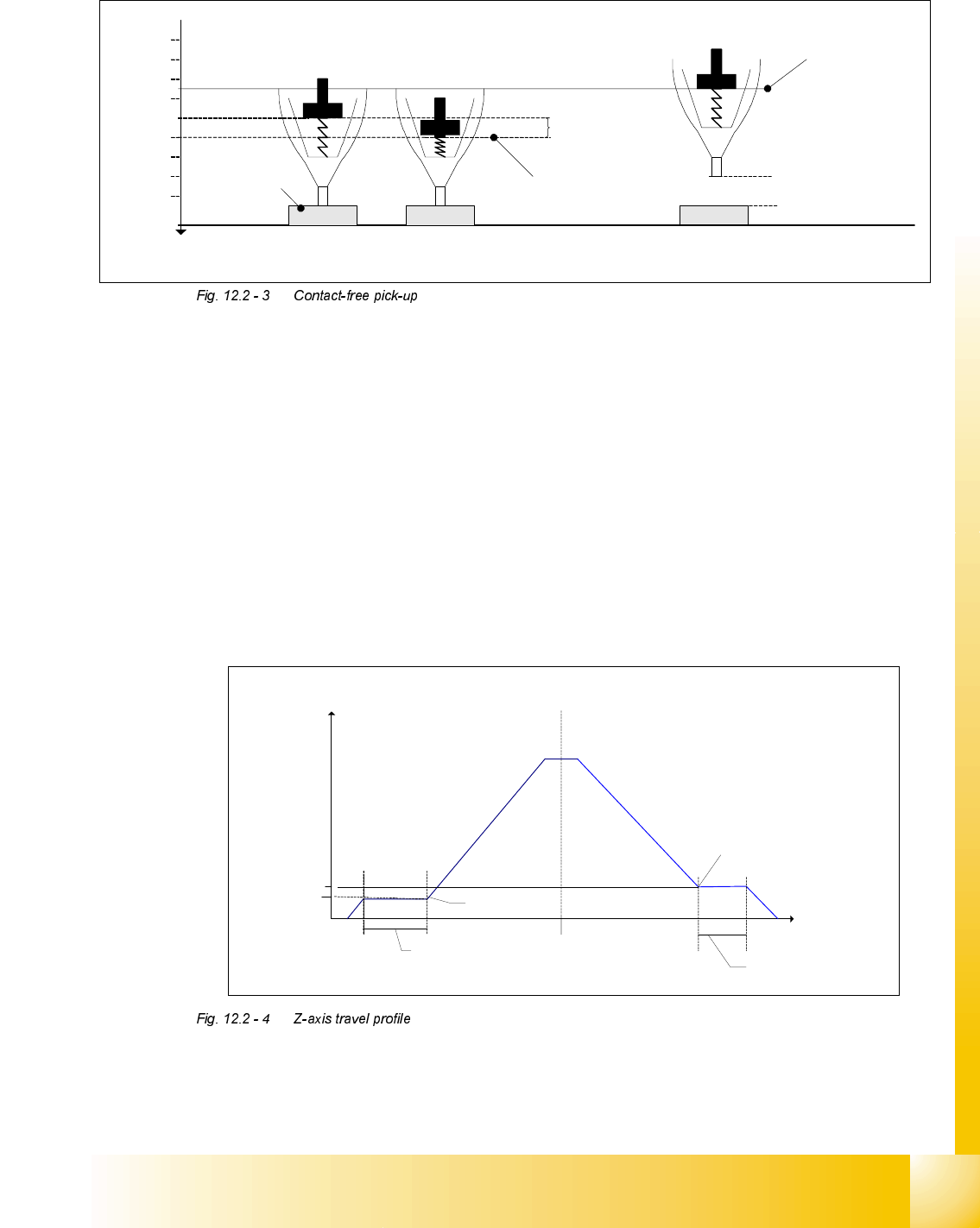
7UDYHOSURILOHRIWKH=D[LV
=D[LVWUDYHOSURILOHGRZQZDUGVRQSLFNXS
0RGHNormal downward motion with light barrier at bottom
0RGHCalibration mode for pick-up without contact
=D[LVWUDYHOSURILOHXSZDUGVRQSLFNXS
0RGHStandard mode
0RGHCreep mode, i.e. the Z-axis moves up slowly the first few millimeters.
0RGHCreep mode, i.e. the Z-axis moves up slowly the first two millimeters.
The figure shows the travel profile for the Z-axis when moving upwards. Using the parameters
V
Start
and S
Start
, a creep path can be set up in the acceleration phase, and with the parameters
V
End
and S
End
in the deceleration phase.
Spring travel
approx.
200 µm
Height
clearance
Pick-up position
Pick-up position
with height
clearance
Pick-up at height
clearance level
Normal pick-up
with light barrier
z
400 µm
200 µm
600 µm
800 µm
1000 µm
1200 µm
1400 µm
1600 µm
1800 µm
Component
Spring travel
approx.
200 µm
Height
clearance
Pick-up position
Pick-up position
with height
clearance
Pick-up at height
clearance level
Normal pick-up
with light barrier
z
400 µm
200 µm
600 µm
800 µm
1000 µm
1200 µm
1400 µm
1600 µm
1800 µm
Component
Z-axis
s
[µm]
v
[m/s]
Acceleration phase Deceleration phase
Creep path
s
Start
V
Start
Creep path
s
End
V
End
V
End
V
Start