HS50_advance_level 2.pdf - 第81页
Stud ent Gu ide HS-5 0 Adva nced II 07/2 002 Ed ition 3 Power Supply 43 3 DUWV 5HPRY LQJF RQW DFWRU 6= DANGER Switc h off the plac ement sy stem and disconn ect from the po wer suppl y (see section…
07/2002 Edition Student Guide HS-50 Advanced II
3 Power Supply
42
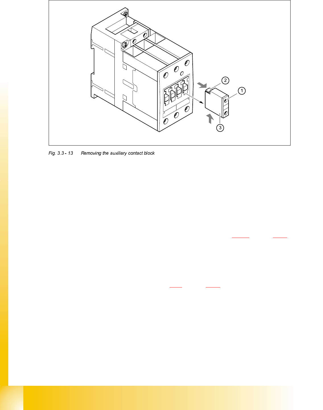
➠ Loosen the clamping screws (1).
➠ Pull the terminal wires up or down to remove and identify with adhesive labels.
➠ Push the grey lug at the top of the auxiliary contact block (2) towards the front panel and hold
in place.
➠ Raise the auxiliary contact block (3) and remove from the slots.
)LWWLQJWKHDX[LOLDU\FRQWDFWEORFN
➠ Check the type of the new auxiliary contact block (see table in section 3.3.9.2 on page 3 - 40).
➠ Insert the auxiliary contact block from the top.
➠ Attach the cable.
➠ Switch the placement system on and start it up, then measure the voltages at the auxiliary con-
tact blocks as per circuit diagram 00336145-XXXXXxLD4.
➠ Complete the servicing work as described in 3.3.3 on page 3 - 29.
5HSODFLQJFRQWDFWRU6=
7RROVDQGHTXLSPHQW
– Set of slotted-head screwdrivers
– Self-adhesive labels
– Digital multimeter
– HS-50 detailed circuit diagrams

Student Guide HS-50 Advanced II 07/2002 Edition
3 Power Supply
43
3DUWV
5HPRYLQJFRQWDFWRU6=
DANGER Switch off the placement system and disconnect from the power
supply (see sections 3.3.1 and 3.3.2).
➠ Remove the suppressor diode Di1 from contactor SZ4.
➠ Loosen the contactor clamping screw (1).
➠ Pull the terminal wires out one by one and identify with adhesive labels.
➠ Insert a screwdriver into the opening (2) in the plastic retainer and lift up slightly.
➠ Tilt the contactor down slightly and remove.
)LWWLQJFRQWDFWRU6=
➠ Place the contactor on the top of the top-hat rail and snap into place.
➠ Connect up the terminal wires.
➠ Fit the suppressor diode Di1.
&RQWDFWRU 'HVLJQDWLRQ ,WHPQXPEHU
SZ4 SIRIUS 3RT13/24 VDC, size S0 00341209-01
Di1 Suppressor diode for contactor SZ4/DL 24-70V 00342396-01
07/2002 Edition Student Guide HS-50 Advanced II
3 Power Supply
44
➠ Switch the placement system on and start it up, then measure the voltages as per the table in
section 3.2.2.2
on page 3 - 12.
➠ Complete the servicing work as described in 3.3.3 on page 3 - 29.
5HSODFLQJPLQLDWXUHFLUFXLWEUHDNHU))
7RROVDQGHTXLSPHQW
– Set of slotted-head screwdrivers
– Digital multimeter
– HS-50 detailed circuit diagrams
3DUWV
5HPRYLQJWKHPLQLDWXUHFLUFXLWEUHDNHU
DANGER Switch off the placement system and disconnect from the power
supply (see sections 3.3.1 and 3.3.2).
0LQLDWXUHFLUFXLWEUHDNHU 7\SH &KDUDFWHULVWLFIHDWXUHV ,WHPQXPEHU
F1 5SX2/1-pole/4A-AC C 00307161-01
F3 5SX2/3-pole/4A-AC C 00302817-01
F4 5SX2/3-pole/32A-AC D 00341203-01
F5, F6, F7, F9 5SX2/1-pole/10A-AC B 00341204-01
F8 5SX2/1-pole6A-AC 00341205-01
F10 5SX2/1-pole/25A-AC C 00341206-01
F11 5SX2/1-pole/1A-AC 00310685-01