HS50_advance_level 2.pdf - 第290页
07/2002 Editio n Student G uide HS -50 Advanc ed II 9 Z-Axis 30 $ [LV G\ QD PLFV NOTE: All SITEST functio ns are e xplaine d by the us e of ga ntry 1 7 RROVDQG7 HVW$ LGV – 2 or 4 ch annel stora ge osci llos…
Student Guide HS-50 Advanced II 07/2002 Edition
9 Z-Axis
29
3URFHGXUH
➠ Turn on the machine.
➠ Connect both channels to the connectors X13, X15 or X16, pin1 respectively.
➠ Set the oscilloscope to "auto" (with trigger).
➠ With the help of the positioning switches of CH1 and CH2, move the oscilloscope ray of CH1
to the center of the screen and the oscilloscope ray of CH2 to the lower edge of the screen.
➠ Change the connection of CH1 to connector X13, X15 or X16 on pin 2 respectively.
➠ Change the connection of CH2 to connector X 13, X15 or X16 on pin 5 respectively.
➠ Set the trigger to "norm" and set the oscilloscope with "trigger" to a suitable triggering
threshold.
➠ Manually, move the appropriate axis back and forth.
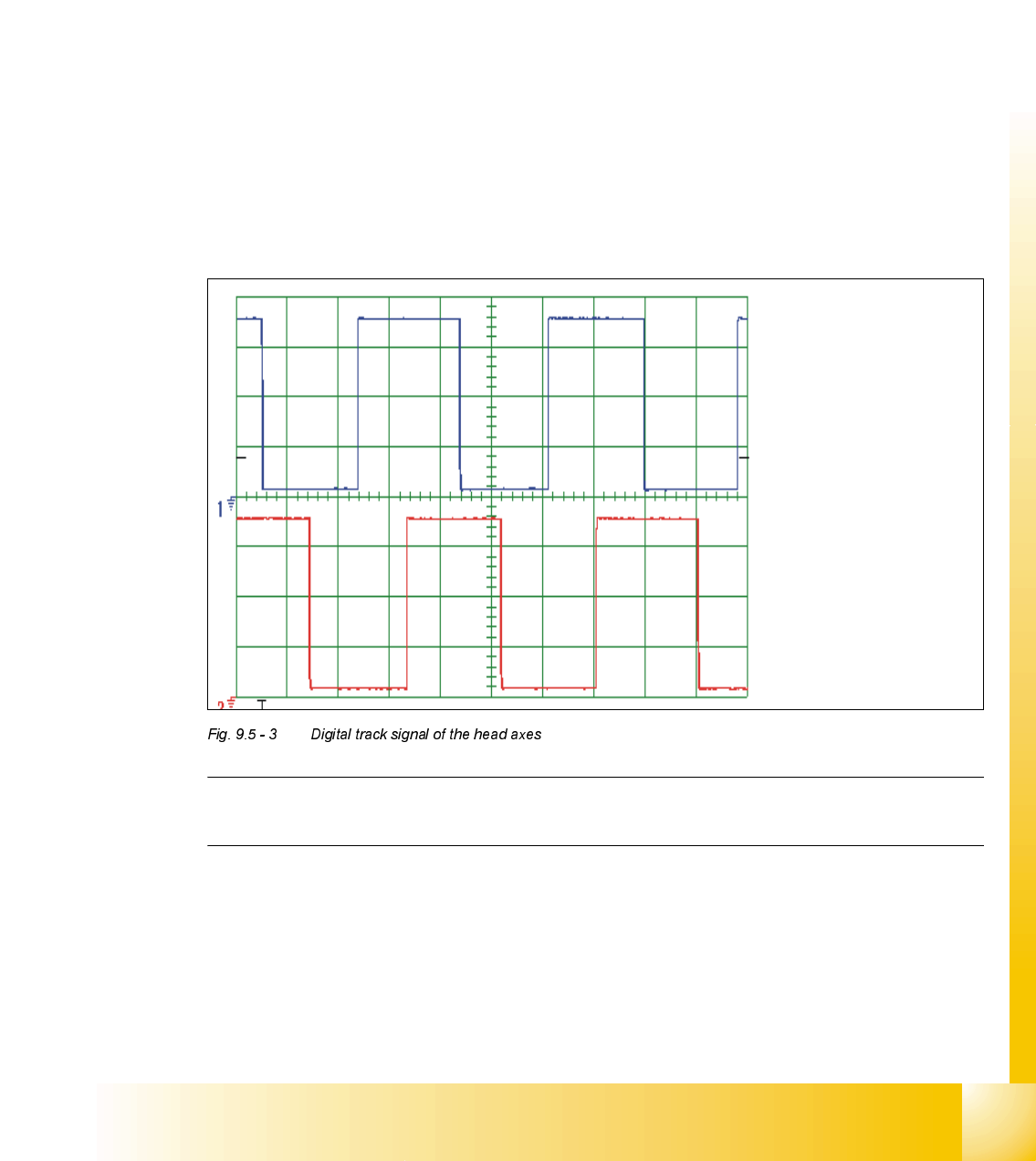
– If you adjusted the read correctly, the following illustration will be displayed on the
oscilloscope screen:
NOTE
Pulse width is dependent on the speed, the phase location is dependent on the direction.
Spur A / track A
Spur B / track B
07/2002 Edition Student Guide HS-50 Advanced II
9 Z-Axis
30
$[LVG\QDPLFV
NOTE: All SITEST functions are explained by the use of gantry 1
7RROVDQG7HVW$LGV
– 2 or 4 channel storage oscilloscope, SIPLACE axis test box, SITEST software.
NOTe: The machine must have reached its operating temperature before you begin to adjust
the axes.Therefore, make sure to switch it on, at least 30 minutes before you begin to work.
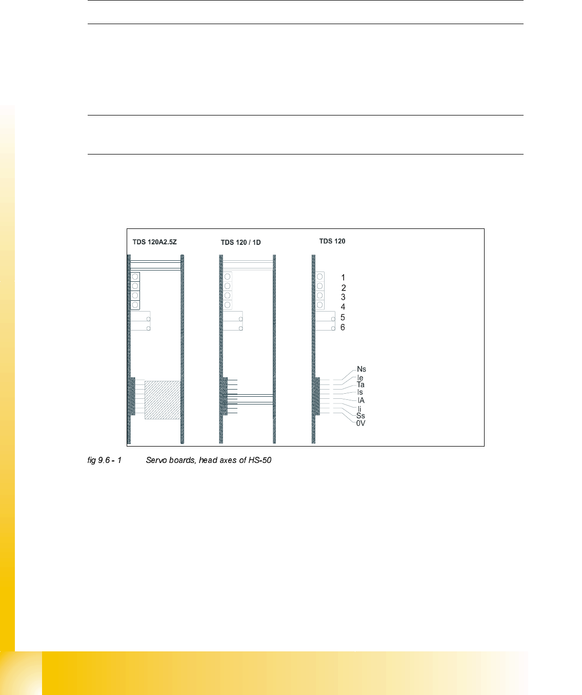
6HUYR%RDUG+HDG$[HV+6
TDS 120 A2.5Z = Servo board z-axis
TDS 120 / 1D = Servo board dp - axis
TDS 120 = Pin configuration
LED: Ready for operation
LED: Enable output stage
LED: Effective current limit
LED: Error
Potentiometer: Tacho
Potentiometer: P-Amplification
Ns Speed setpoint value
Ie Setpoint value, power input
Ta Tacho (real tacho voltage)
Is Nominal current (speed controller output)
IA Motor manipulated variable (speed con troller output)
li Actual current
Ss Sensor stop signal
0V Amplifier electronic GND
Student Guide HS-50 Advanced II 07/2002 Edition
9 Z-Axis
31
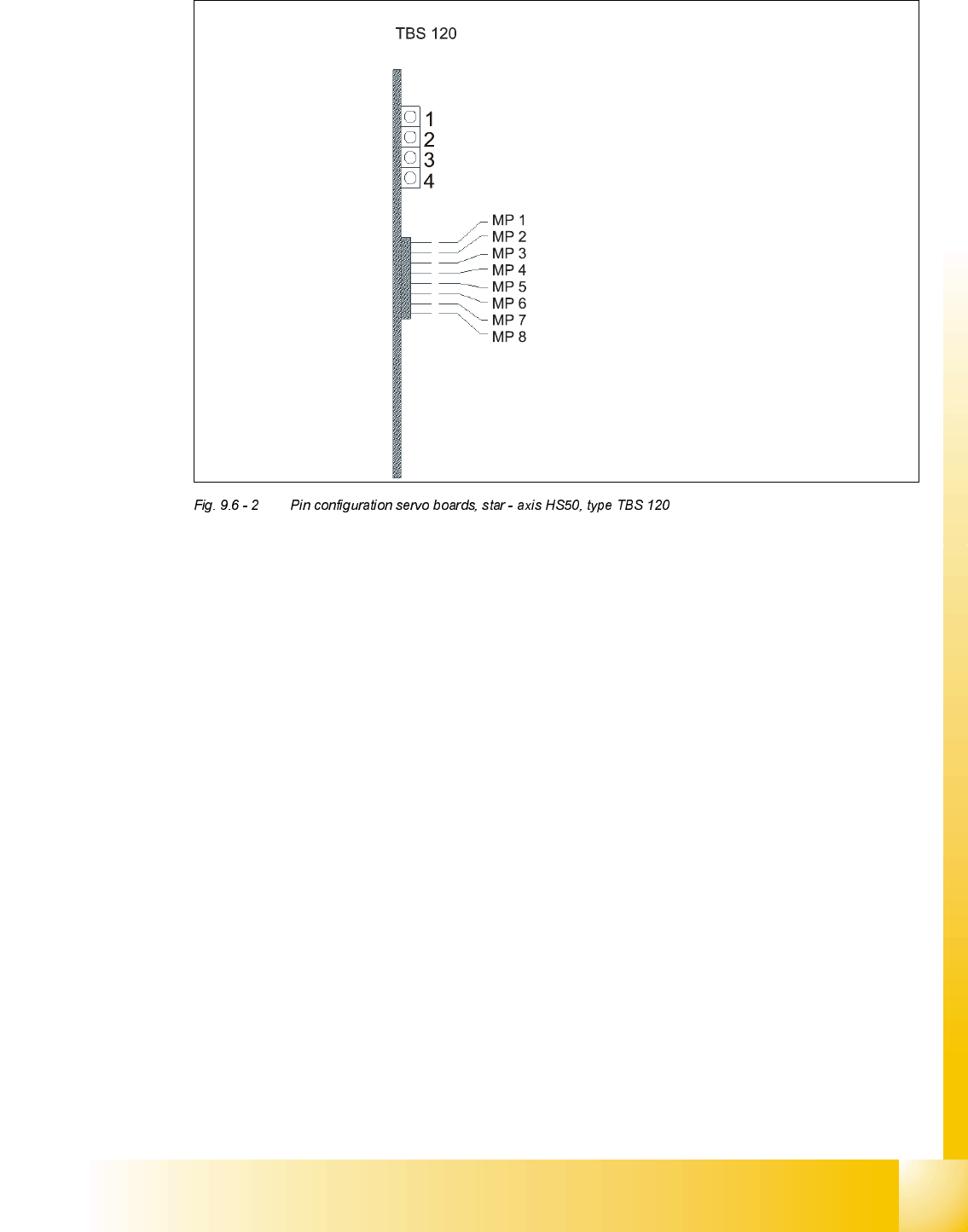
.(<
(1) LED: Ready for operation
(2) LED: Enable output stage
(3) LED: I
RMS
limit
(4) LED: Error
MP1 = Nominal current "I-S (U)"
MP2 = Nominal current "I-S (W)"
MP3 = Actual current "I-ist (U)"
MP4 = Actual current "I-ist (W)"
MP5 = "U-nominal (U)"
MP6 = "U-nominal (W)"
MP7 = Free
MP8 = Reference potential "0V"