HS50_advance_level 2.pdf - 第77页
Stud ent Gu ide HS-5 0 Adva nced II 07/2 002 Ed ition 3 Power Supply 39 5HS ODFLQJFRQW DFWRUV6=6= DQG6 = 7 RROVDQ GHTXLSPH QW – Set of sl otted-hea d scre wdrivers – Self-ad hesi…
07/2002 Edition Student Guide HS-50 Advanced II
3 Power Supply
38
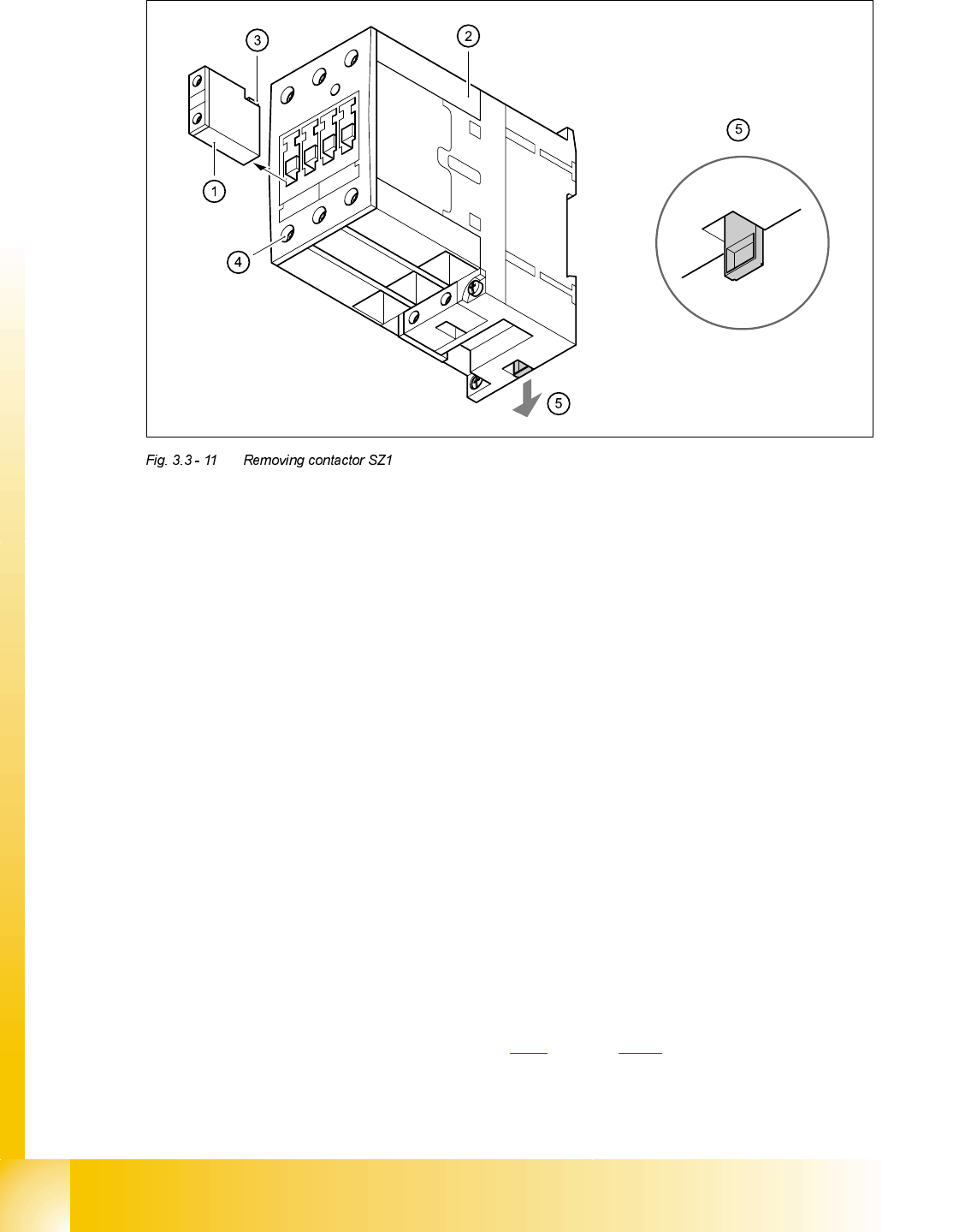
➠ Remove auxiliary contact blocks K11, K12 and K14 from contactor SZ1.
➠ To do this, push the lug (3) on the top of the auxiliary contact block towards the front panel and
hold in place.
➠ Raise the auxiliary contact blocks (1) and remove from the slots.
➠ Loosen the clamping screws (4) on contactor SZ1.
➠ Pull the terminal wires out one by one and identify with adhesive labels.
➠ Use the screwdriver to press down the locking lug (5) on the back of the contactor.
➠ Tilt the contactor upwards and detach from the top-hat rail.
)LWWLQJFRQWDFWRU6=
➠ Attach the contactor to the top edge of the top-hat rail.
➠ Push down on the contactor until it snaps into place.
➠ Check that it is firmly seated.
➠ Connect up the terminal wires.
➠ Insert auxiliary contact blocks K11, K12 and K14 from the top and snap into place.
➠ Switch the placement system on.
➠ Test the 24 VDC control voltage between terminals A1 and A2.
➠ Test the supply voltage between terminals L1, L2, L3 and T1, T2 and T3.
➠ Complete the servicing work as described in 3.3.3 on page 3 - 29.
Student Guide HS-50 Advanced II 07/2002 Edition
3 Power Supply
39
5HSODFLQJFRQWDFWRUV6=6=DQG6=
7RROVDQGHTXLSPHQW
– Set of slotted-head screwdrivers
– Self-adhesive labels
– Digital multimeter
– HS-50 detailed circuit diagrams
3DUWV
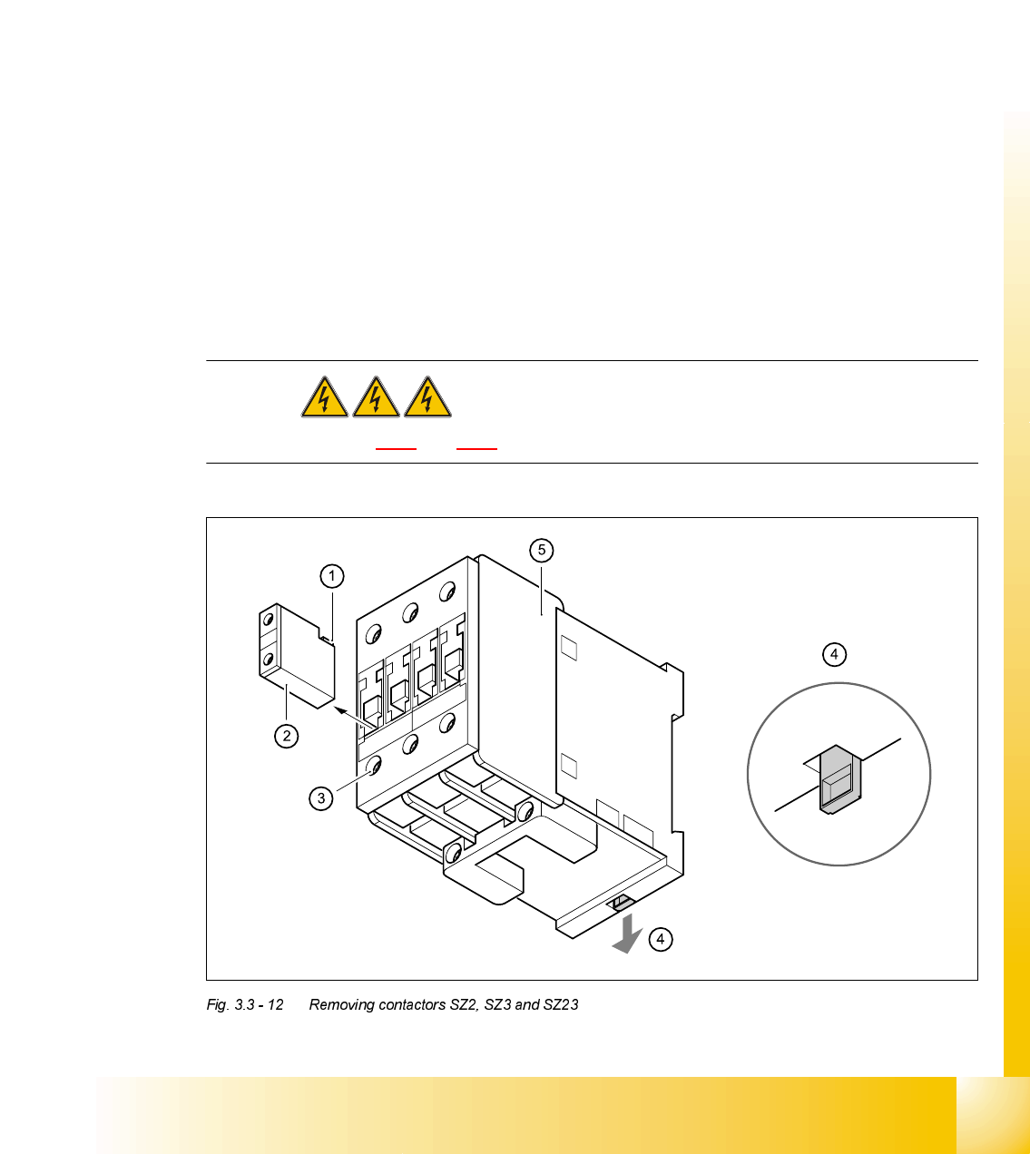
5HPRYLQJFRQWDFWRUV6=6=DQG6=
DANGER Switch off the placement system and disconnect from the power
supply (see sections 3.3.1 and 3.3.2).
&RQWDFWRU 'HVLJQDWLRQ ,WHPQXPEHU
SZ2 SIRIUS 3RT10/24 VDC, size S0 00341208-01
SZ3 SIRIUS 3RT10/24 VDC, size S0 00341208-01
SZ23 SIRIUS 3RT10/24 VDC, size S0 00341208-01

07/2002 Edition Student Guide HS-50 Advanced II
3 Power Supply
40
➠ Remove the auxiliary contact blocks
➠ Push the lug (1) at the top of the auxiliary contact blocks towards the front panel and hold in
place.
➠ Lift the auxiliary contact blocks (2) and remove from their slots.
➠ Loosen the contactor clamping screws (3).
➠ Pull the terminal wires out one by one and identify with adhesive labels.
➠ Use the screwdriver to press down the locking lug (4) on the back of the contactor.
➠ Tilt the contactor (5) upwards and detach from the top-hat rail.
)LWWLQJFRQWDFWRUV6=6=DQG6=
➠ Attach the contactor to the top edge of the top-hat rail.
➠ Push down on the contactor until it snaps into place.
➠ Connect up the terminal wires.
➠ Snap the auxiliary contact blocks into place on SZ2, SZ3 and SZ23.
➠ Switch the placement system on and start it up, then measure the voltages shown in the table
in section 3.2.2.2
on page 3 - 12.
➠ Complete the servicing work as described in 3.3.3 on page 3 - 29.
5HSODFLQJDX[LOLDU\FRQWDFWEORFNV.[.[.[
7RROVDQGHTXLSPHQW
– Set of slotted-head screwdrivers
– Self-adhesive labels
– Digital multimeter
– HS-50 detailed circuit diagrams
3DUWV
K21, K22, K23, K24 from SZ2
K31, K32, K33, K34 from SZ3
K232, K234 from SZ23
'HVLJQDWLRQ ,WHPQXPEHU
Auxiliary contact block 3RT1/1-pole/1 NC 00341210-01
(K11, K12, K24, K34, K234)
Auxiliary contact block 3RT1/1-pole/1 NO 00341221-01
(K14, K21, K22, K23, K31, K32, K33, K232)