HS50_advance_level 2.pdf - 第279页
Stud ent Gu ide HS-5 0 Adva nced II 07/2 002 Ed ition 9 Z-Axis 19 9

07/2002 Edition Student Guide HS-50 Advanced II
9 Z-Axis
18
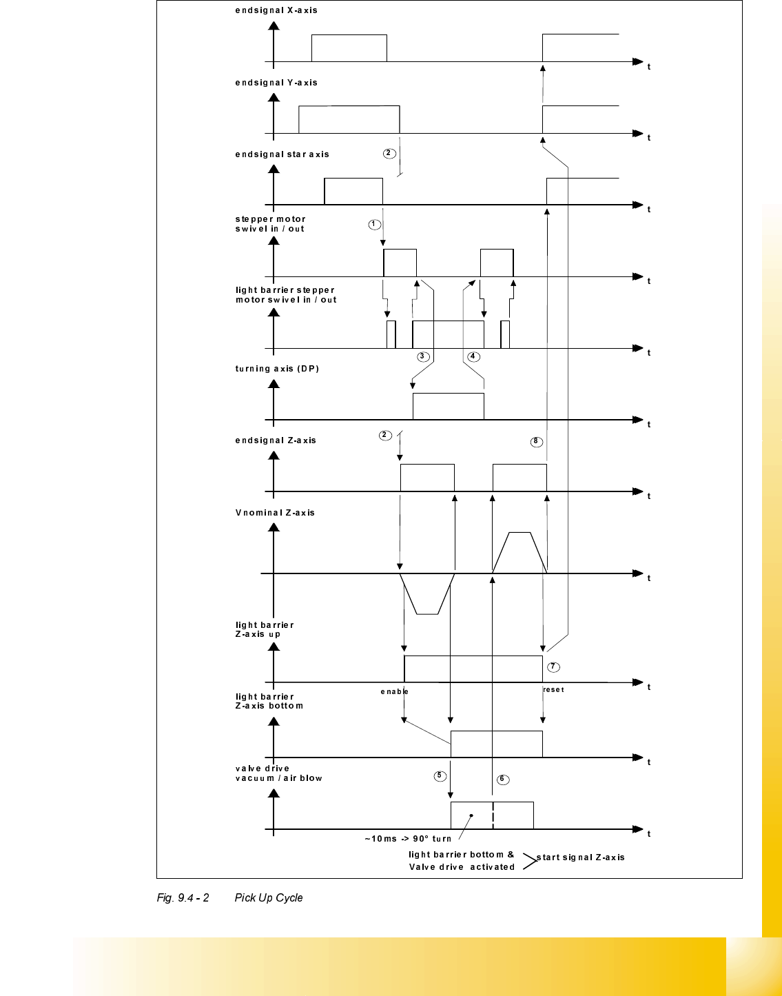
6LJQDO7LPLQJ&KDUWRQWKH&ROOHFW3ODFH+HDG3LFN8S&\FOH
a The end signal of the star axis starts the swivel - in function at the dp-station.
s The last end signal from the X- Y- or star axis and the OK-message "feeder ready" starts the
movement downward of the Z-axis.
d The end signal of the swivel in - function starts the dp-axis for an empty segment and prepares
the pick - up angle for this segment.
f The end signal of the dp-axis starts the swivel - out function.
g The end signal of the Z-axis on the bottom (light barrier) starts the stepper motor vacuum- / air
kiss valve (the stepper motor rotates by 180° to connect the vacuum channel to the segment).
h The 90 degree movement signal of the stepper motor starts the Z-axis upwards. The stepper
motor continue moving until reached 180 degree.
j The light barrier Z-axis in upper position disables the light barrier signal on the bottom and
starts the gantry axes. At this point the vacuum check for pick - up of a component is per-
formed.
k The end signal of the Z-axis on top (0-position) starts the star axis.
Student Guide HS-50 Advanced II 07/2002 Edition
9 Z-Axis
19
9

07/2002 Edition Student Guide HS-50 Advanced II
9 Z-Axis
20
3LFNXS&\FOHZLWKVSHFLDOPRGHV
The special Z-axis modes "early vacuum" and "slow start upwards" explaind here in combination.
This combined usage could be programmed - but for the placement process it make less sense.
The slow start upwards (after pick up) is used with less than 100% acceleration of Z-Axis.
The slow start upwards take typically 20 ms longer!
1) The start of the pick up cycle is like the standard pick up cycle.
2) The last end signal from the X- Y- or Star axis and the OK-message "feeder ready" start the Z-
axis movement downward.
3) The upper light barrier switch the valve drive for the vacuum on when in the GF-Editor the but-
ton " Early Vacuum" is activeted. During the travel down timevacuum came to the open top of the
nozzle. At tiny nozzles you have a relatively high vacuum to suck the component on the nozzle.
Unfortunately the nozzle is open to suck dust from the environment (so not recomended for large
nozzles).
4) The slope at the upper light barrier enable the lower light barrier function. (see standard mode
diagram before
5) The end signal of the valve drive and the Z-axis on lower position (light barrier) start the Z- axis
with minimum speed for a 1 mm distance, if you used the right travel profil in the GF-Editor.
6) At this time of about 20 ms the vacuum between component and nozzle increase to the maxi-
mum. Than the Z-axis move on with standard speed profile (acceleration).
7) The signal of the upper light barrier switch off the signal of the lower light barrier and start the-
vacuum check after pick up and X- Y- movement.
8) The endsignal of the Z-axis (at 0-position) start the Star- axis.