HS50_advance_level 2.pdf - 第189页
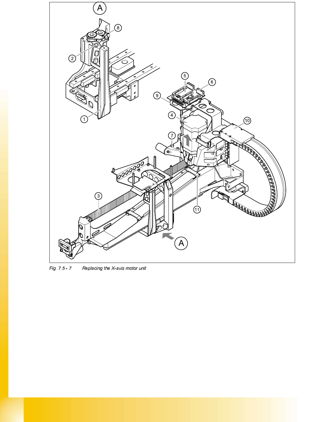
Stud ent Gu ide HS-5 0 Adva nced II 07/2 002 Ed ition 7 X- Axis 31 ,QVW DOOLQJ WKH;D[ LVPRWRU XQLW *DQWU\RU ➠ Caref ully inse rt the X-ax is motor unit (i tem 4 in Fig. 7.5 - 7 ) as far as the s top…
07/2002 Edition Student Guide HS-50 Advanced II
7 X-Axis
30
(1) Head mount
(2) M4 x 35 hexagon socket-head screw for tensioning the X-axis toothed belt
(3) Synchroflex X-axis toothed belt
(4) X-axis motor unit
(5) X/Y distributor
(6) X5 socket for X-axis motor
(7) 2 x M6 x 14 hexagon socket-head screws
(8) Locknut
(9) Board holder
(10) Cable holder
(11) Cable clamp
Student Guide HS-50 Advanced II 07/2002 Edition
7 X-Axis
31
,QVWDOOLQJWKH;D[LVPRWRUXQLW
*DQWU\RU
➠ Carefully insert the X-axis motor unit (item 4 in Fig. 7.5 - 7) as far as the stop, making sure that
you do not damage the toothed belt. The motor cable points towards the permanent magnets
of the linear drive.
➠ Use the two hexagon socket-head screws (item 7 in Fig. 7.5 - 7) to clamp the X-axis motor unit.
➠ Fit the cable holder for the trailing cable (item 10 in Fig. 7.5 - 7).
➠ Fit the board holder (item 9 in Fig. 7.5 - 7).
➠ Fit the X/Y distributor (item 5 in Fig. 7.5 - 7).
➠ Plug in all plugs into their socket on the X/Y distributor (item 5 in Fig. 7.5 - 7).
➠ Use the cable clamp (item 11 in Fig. 7.5 - 7) to fix the flat ribbon cable.
➠ Use cable ties to fix all cables.
CAUTION
Make sure that the cables are firmly seated. Otherwise, the high acceleration forces may
cause the cable to slip out of position and shear through.
➠ Turn the hexagon socket-head screw (item 2 in Fig. 7.5 - 7) to pre-tension the X-axis toothed
belt.
➠ Use the three M6 x 8 hexagon socket-head screws to fit the black cover strip to the cross-beam
above the gantry concerned.
➠ Connect the cable of the fan motor to the socket.
*DQWU\RU
➠ Carefully insert the X-axis motor unit (item 4 in Fig. 7.5 - 7) as far as the stop, making sure that
you do not damage the toothed belt. The motor cable points towards the permanent magnets
of the linear drive.
➠ Use the two hexagon socket-head screws (item 7 in Fig. 7.5 - 7) to clamp the X-axis motor unit.
➠ Fit the cable holder for the trailing cable (item 10 in Fig. 7.5 - 7).
➠ Fit the board holder (item 9 in Fig. 7.5 - 7).
➠ Plug in the X-motor plug into its socket on the X/Y distributor (item 5 in Fig. 7.5 - 7).
➠ Use the cable clamp (item 11 in Fig. 7.5 - 7) to fix the flat ribbon cable.
➠ Use cable ties to fix all cables.
07/2002 Edition Student Guide HS-50 Advanced II
7 X-Axis
32
CAUTION
Make sure that the cables are firmly seated. Otherwise, the high acceleration forces may
cause the cable to slip out of position and shear through.
➠ Turn the hexagon socket-head screw (item 2 in Fig. 7.5 - 7) to pre-tension the X-axis toothed
belt.
➠ Use the three M6 x 8 hexagon socket-head screws to fit the black cover strip to the cross-beam
above the gantry concerned.
➠ Connect the cable of the fan motor to the socket.
6HWWLQJV
➠ Push the head mount (item 1 in Fig. 7.5 - 7) towards X-axis motor unit as far as the stop on the
elastomeric spring.
➠ Turn the hexagon socket-head screw (item 2 in Fig. 7.5 - 7) to set the belt tension to 53 Hz +
1/-3 Hz.
CAUTION
Do not overstretch the toothed belt when adjusting the belt tension.
➠ Secure the hexagon socket-head screw (item 2 in Fig. 7.5 - 7) with the locknut (item 8 in Fig.
7.5 - 7
).