HS50_advance_level 2.pdf - 第146页
07/2002 Editio n Student G uide HS -50 Advanc ed II 6 Cont rol & C ommun icatio n 16 7 UDFN$DQG,QYHUW HG$ VLJQD OWKHRU\$ OVRIRU %DQG,QY HUWHG% The track signal A is prep ared to be send d o wn …
Student Guide HS-50 Advanced II 07/2002 Edition
6 Control & Communication
15
'LJLWL]DWLRQDQG0XOWLSOLFDWLRQRIWKH$QDORJXH7UDFN6LJQDOV
Phase shift check on possible count errors.
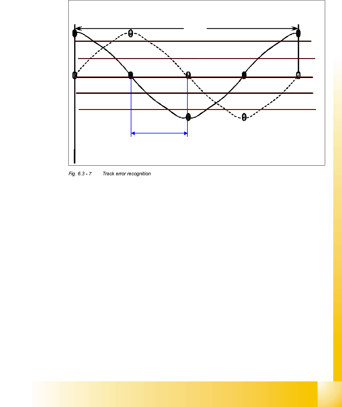
7UDFNHUURUUHFRJQLWLRQDWDQDORJXHVLJQDO
5,12 cm
The tolerance at the analogue signal of the track signal is checked according the limit of
90° +/- 15°
90° +/- 15°.
07/2002 Edition Student Guide HS-50 Advanced II
6 Control & Communication
16
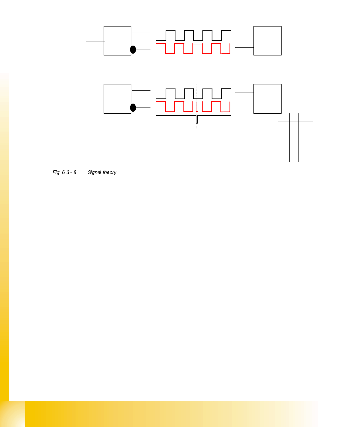
7UDFN$DQG,QYHUWHG$VLJQDOWKHRU\$OVRIRU%DQG,QYHUWHG%
The track signal A is prepared to be send down to axis controller
= 1
A
∀
A
A buffer and an inverter amplifies the rectangular track signal A and the inverted signal
∀.
To detect a transmission error in the machine we invert the generated track signal. If the
two signal lines at axis controller always have an inverted state the count pulses are
correct.
= 1
A
∀
A
If an error occurs in the wiring the EXOR logic (exclusive OR logic gate)
recognizes this. Therefore the axis card will signal a counting error.
A
∀
Q
0 0 0
0 1 1
1 0 1
1 1 0
Output
Student Guide HS-50 Advanced II 07/2002 Edition
6 Control & Communication
17
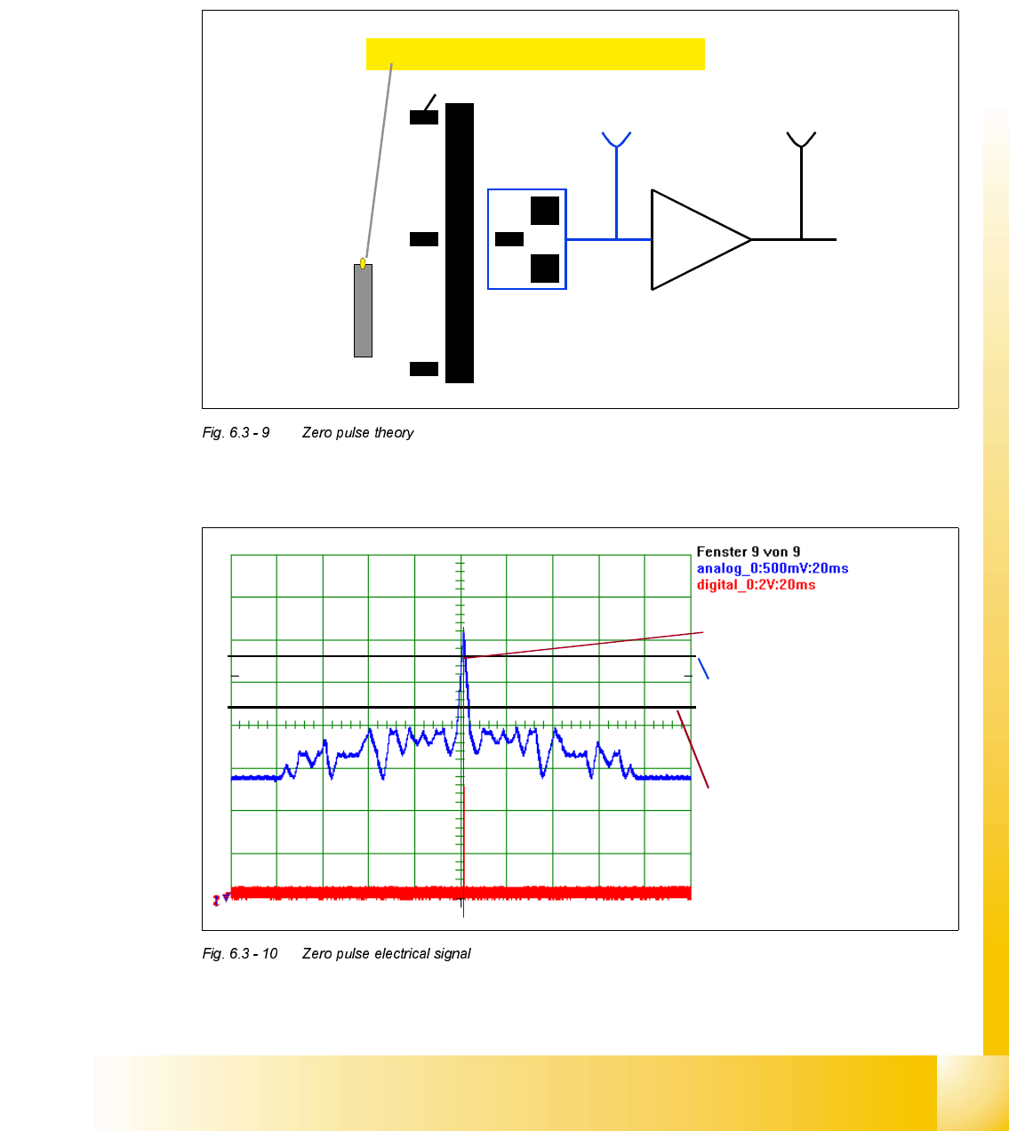
=HUR3XOVH7KHRU\
The Zero pulse of the axes is a singular signal in the whole travel range. This defines the “home
position” where position counting starts. On the X & Y axes the Zero pulse is repeated within the
travel range, however only one signal is used. During the reference run this zero pulse window is
detected with help of proximity switches (Bero).
=HURSXOVHHOHFWULFDOVLJQDOVHHQRQDQRVFLOORVFRSH
Zero pulse window (repeated)
Proximity switch (Bero)
At 2,7 V the Schmitt Trigger-
circuit generates the digital
Zero pulse signal.
The analogue Zero pulse
should override this threshold.
Interference pulses should not
override this limit.