HS50_advance_level 2.pdf - 第412页
07/2002 Editio n Student G uide HS -50 Advanc ed II 14 Conveyor System 38 ([F KDQJLQJW KH/RQJ7 RRWKHG%HOWRIW KH: LG WK $ GMXVWPHQW6\VWHP ➠ Remove the lifting ta ble as de scribe d in sec tion 14 .3.8.1…

Student Guide HS-50 Advanced II 07/2002 Edition
14 Conveyor System
37
➠ Remove all tools, etc., form the working area of the machine.
➠ Fold the transmission lever on the lifting table motor GRZQ (see Fig. 14.3.5: illustration bottom
left).
➠ Install the lifting table plate as described in section 14.3.8.2.
➠ Carry out the pertinent )LQDOVWHSVLQFOXGLQJWKHIXQFWLRQFKHFN.
([FKDQJLQJWKH3UR[LPLW\6ZLWFKIRU/LIWLQJ7DEOH8S3UR[LPLW\6ZLWFK
IRU/LIWLQJ7DEOHGRZQ
5HPRYLQJWKH3UR[LPLW\6ZLWFKIRU/LIWLQJ7DEOH8SDQGRU'RZQ
➠ Remove the lifting table as described in section 14.3.8.1.
➠ Remove the faulty proximity switch for "Lifting table down" or "Lifting table up" from the motor
mount as described in section 14.3.9.1.
– If both proximity switches are faulty, label the allocation "up" / "down" before removing them.
➠ Unplug the cableRQthe lifting table proximity switch which is to be removed (X5 / X6; X8/ X9
-> see circuit diagram of6/,2PRGXOHRQ3&%FRQYH\RU or
RQ3&%FRQYH\RU. See NOTE below.
NOTE:
If you have discovered a break in the proximity switch cable during a continuity check, the prox-
imity switch cable must be run on a weaving course as far as the SLIO module (layout: see ) and
unplugged at the corresponding connector of the SLIO module on conveyor 1 or 2 (X1 / X2, X4 /
X 5: see above-mentioned circuit diagrams). This may be somewhat complicated depending on
the routing of cables inside the machine base.
You may wish to contact Siemens SMD Service regarding this work. 14
,QVWDOOLQJWKH3UR[LPLW\6ZLWFKIRU/LIWLQJ7DEOH8SDQGRU'RZQ
➠ Use the two m3 hexagonal socket head cap screws on the motor mount to fasten the new prox-
imity switch(es), to the motor mount with the correct allocation "up" / "down" (see Fig. 14.3.5).
➠ Mount the plug-and-socket connector on the new proximity switch(es).
➠ Remove all tools, etc., from the working area of the machine.
➠ Move the transmission lever on the lifting table motor down to the lifting curve (see Fig. 14.3.5,
illustration bottom left).
➠ Re-install the lifting table as described in section 14.3.8.2.
➠ Using the SITEST program, conduct a function check of the proximity switches.
07/2002 Edition Student Guide HS-50 Advanced II
14 Conveyor System
38
([FKDQJLQJWKH/RQJ7RRWKHG%HOWRIWKH:LGWK$GMXVWPHQW6\VWHP
➠ Remove the lifting table as described in section 14.3.8.1.
➠ With the aid of open-end wrenches (5,5 and 8) relieve the tension on the long toothed belt on
the HFFHQWULFD[LVof the "Drive unit for the width adjustment system" (see Fig. 14.3.7 ->).
CAUTION O
The pressure flange on the bearing housing is not loosened for this step. However, if you must
loosen the pressure flange, e.g., to exchange the bearing housing (if ball bearing faulty), you must
always restore the parallelism of the conveyor as described in section 14.4. 14
➠ Remove the long toothed belt by taking it off the deflection pulley (see Fig. 14.3.7 -> 3) on the
"Drive unit for width adjustment system" and from the two external synchronizing disks on the
pertinent bearing housing.
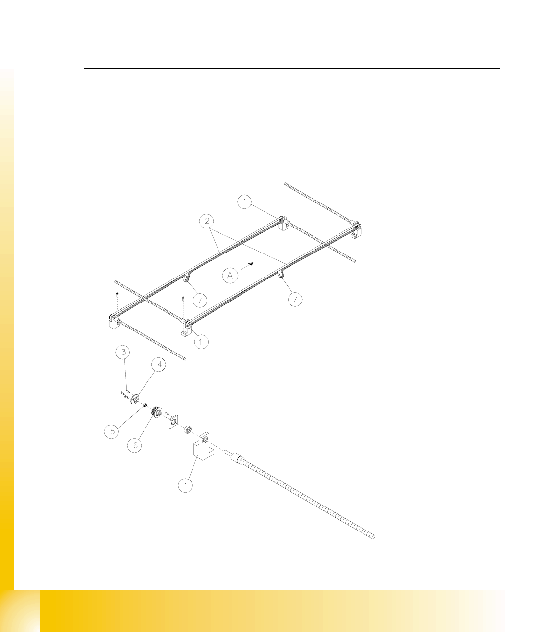
5HPRYLQJD7RRWKHG%HOWIRUWKH:LGWK$GMXVWPHQW6\VWHP/RQJ
Fig. 14.3.6 Width Adjustment System: Layout of the Long Toothed Belt, Removing

Student Guide HS-50 Advanced II 07/2002 Edition
14 Conveyor System
39
Key to Fig. 14.3.6
,QVWDOOLQJD7RRWKHG%HOWIRUWKH:LGWK$GMXVWPHQW6\VWHP/RQJ
CAUTION O
The new toothed belt is not to be stretched or kinked. 14
➠ Place the new toothed belt (synchronizing belt BRECO) on the two synchronizing disks on the
recirculating spindles and weave the belt in via the deflection pulleys on the drive unit.
➠ Place tension on the toothed belt on the eccentric axis (see Fig. 14.3.7 -> 2) of the "Drive unit
for the width adjustment system" until it reliably engages in the teeth of the synchronizing disk.
Check: The entire width of the toothed belt must be engaged with the synchronizing disk.
and it must be in contact with the circumference of the deflection pulleys on its entire width.
➠ Remove all tools, etc., in the working area of the machine.
➠ Make certain that the transmission lever on the lifting table motor mount is folded onto the lift-
ing curve (see Fig. 14.3.5, illustration bottom left).
➠ Re-install the lifting table as described in section 14.3.8.2.
➠ Carry out the )LQDOVWHSVLQFOIXQFWLRQFKHFN (see section 14.4).
During the function check, move the conveyor to its maximum and minimum width.
([FKDQJLQJD7RRWKHG%HOWIRUWKH'ULYHRIWKH:LGWK$GMXVWPHQW6\VWHP
6KRUW
5HPRYLQJWKH7RRWKHG%HOW'ULYHIRUWKH:LGWK$GMXVWPHQW6\VWHP6KRUW
An overview of the layout of the "Drive unit for the width adjustment system" in conveyor 1 and 2
is shown in . 14
A) PCB transport direction
1) Bearing housing, width adj. system
conveyor 1 or 2
2) Toothed belt width adj. system:
Synchronizing belt BRECO
3) 3 Slotted screws M3 x 6 4) Pressure flange, width adjustment system
S50
5) Annular spring (tensioning element) 6) Synchronizing disk
7) Engagement of the toothed belt in the syn-
chronizing disk of the drive unit.
Eccentric axis to relieve teh tension of
toothed belt (see Fig. 14.3.7)