HS50_advance_level 2.pdf - 第286页
07/2002 Editio n Student G uide HS -50 Advanc ed II 9 Z-Axis 26 &KHFNLQJ WKHWUDFN VLJQDOV 7 HVWLQJ7 RROV – One 2-cha nnel stor age osc illoscope > 20 MHz – T est pi ns 1. 4 mm, 1.5 mm and 1.6 mm …
Student Guide HS-50 Advanced II 07/2002 Edition
9 Z-Axis
25
&XUUHQW6HQVRU0RGH
This mode is used for the placement of components that have a programmed placement force of
3 - 10 in the GF editor at the line computer. When the Z axis touches down with the component
onto the PCB the motor continues to try drive the Z-axis down. As a result the motor has to work
harder as the resistance to movement increases. Due to this increase the motor current will start
to rise and the servo card can detect this. Therefore the current sensing circuit can determine the
amount of downward force being applied by the motor and when it reaches the programmed level
the ’End Signal’ is given and the motor stops moving.
6WDQG6WLOO&KHFN
This mode will be used for the mode "contactless pick up" and her only for the calibration the clear-
ance, additionally as a back up should the Current sensing mode fail to give an ’End Signal’. The
axis card is detecting axis movement via the rotary encoder fixed to the motor shaft. If the axis
card does not detect any movement, due to the Z-axis pressing hard on to the PCB, for more than
10 msec it will output the ’End Signal’. This prevents the dangerous situation of the machine stall-
ing with the Z-axis in the down position.
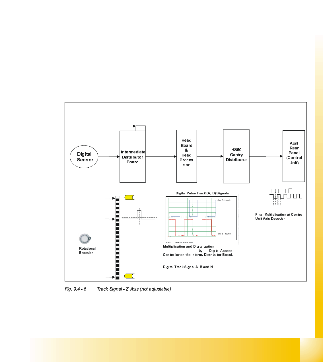
Track Signal - Z Axis (not adjustable)
X13
Connection Point for Track Signal
Test Box
v
v
v
v
Min (Up Position)
= -20 Pulses
Reference Point Counting
OriginLocation of Zero Pulse
Signal, N
Max (Down Position)
= 1000 Pulses
scale
Light Barrier Top
Light Barrier Bottom
of the Analogue
Track Signals A, and B
the
(Multiplication by a factor of 10 for Digital Conversion)
(zero pulse) sent to
Interm. Distributor Board.
3.6 Vpp
X4as
(5) A
(9) B
(1) GND
(7) +5V
X1as X14ac
(39) A
(38) A not
(36) B
(35) B not
(33) N
(32) N not
X3ac X3aa
(33) A
(32) A not
(30) B
(29) B not
(27) N
(26) N not
X26aa X1tp
(2) A
(3) A not
(5) B
(6) B not
(8) N
(9) N not
.
(Multiplication by factor of 4)
So the Z axis movement is a
linear one but the encoder disk
a rotational one the resulution
cannot be calculated as easy
as on the other axis. The end
result of the axis is:
44,2 pulses / 1 mm of scale
Therefore ....
1 digit = 22,62µm
12341234…..

07/2002 Edition Student Guide HS-50 Advanced II
9 Z-Axis
26
&KHFNLQJWKHWUDFNVLJQDOV
7HVWLQJ7RROV
– One 2-channel storage oscilloscope > 20 MHz
– Test pins 1.4 mm, 1.5 mm and 1.6 mm
2YHUYLHZ
$[HV $GMXVWPHQW 2VFLOORVFRSH'LVSOD\
star none pulse signal amplitude 3.6V
ss
z none pulse signal amplitude 3.6V
ss
dp read head on 1.5 mm,
parallel to glass pane
pulse signal amplitude 3.6V
ss
Student Guide HS-50 Advanced II 07/2002 Edition
9 Z-Axis
27
'LJLWDO7UDFN6LJQDOVRIWKH+HDG$[HV
0HDVXUHPHQWRIWKH7UDFN6LJQDOVRI6WDU=DQG'3$[HVDWWKH,QWHUPHGLDWH'LVWULEXWRU
63
; = z-axis
; = star - axis
; = dp - axis
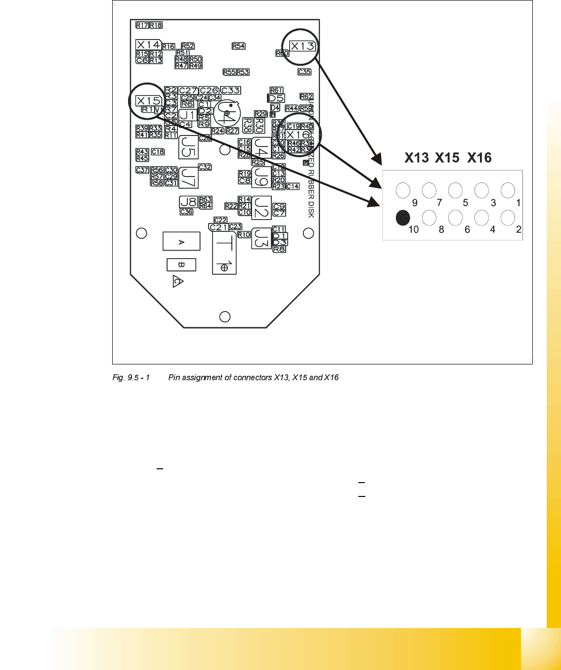
3LQDVVLJQPHQW
1. Ground 2. Track A
3. Track A
4. Ground
5. Track B 6. Track B
7. Track N 8. Track N
9. -4V 10.removed