CP-7-series Verification System Instruction manual(2.0E).pdf - 第125页
15. Explanation of Operation Screens Edition 2.0 114 CP-7-series V erification System Instruction Manual 15.2 [Read Feeder ID] Screen Function This screen is used for r eading the feeder IDs attached to feeders. Although…
15. Explanation of Operation Screens
Edition 2.0 113 CP-7-series Verification System Instruction Manual
Screen access
Screen Explanation
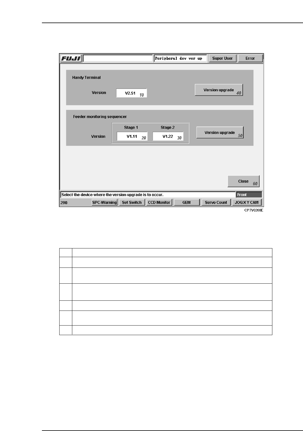
10
Version number of the Handy Terminal currently connected to the machine.
Version number of the feeder mount/demount monitoring sequencer currently
connected to the machine’s stage 1 side.
20
Version number of the feeder mount/demount monitoring sequencer currently
connected to the machine’s stage 2 side.
30
ExplanationNo.
40
Upgrades Handy Terminal’s control application version.
50
Upgrades the feeder mount/demount monitoring sequencer’s control application
version.
60
Returns to the [Maintenance] screen.
VT013E
15. Explanation of Operation Screens
Edition 2.0 114 CP-7-series Verification System Instruction Manual
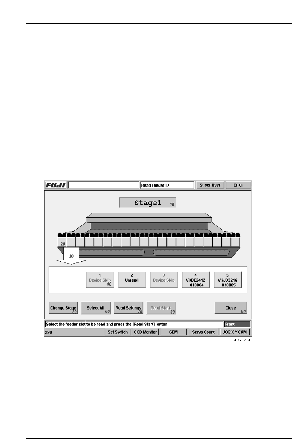
15.2 [Read Feeder ID] Screen
Function
This screen is used for reading the feeder IDs attached to feeders.
Although feeder ID reading usually occurs when automatic operation begins, this screen
enables the reading function to be executed by itself, without starting operation.
In the quick verify mode, parts cannot be verified until the feeder ID is read, and the reel
information is obtained from Fujitrax Verifier. Therefore, it is not possible to know if the
correct feeders are set until automatic operation begins.
This display screen offers a way around this restriction, providing an easy way to check the
part setup without having to begin production.
Input
• To display the Feeder ID Reading screen, press the [Read Feeder ID] button at the
[Main] screen.
• Display of the [Read Feeder ID] screen is only possible if the [Use Fujitrax Verifier]
button is selected at the [Parts Administration System] screen.
Screen Access
15. Explanation of Operation Screens
Edition 2.0 115 CP-7-series Verification System Instruction Manual
Screen Explanation
10
Indicates the current Stage number.
Display area for all slots.
Indicates the feeder ID reading status for all slots of one Stage.
Green
Yellow
Red
: Reading completed.
: Reading is enabled, but has not yet occurred.
: Reading is disabled (feeder not set, etc.).
Green : Indicates that reading is completed. The feeder ID where reading
occurred is indicated on the button.
Yellow : Reading is enabled, but has not yet occurred.
Red : Reading is disabled (feeder not set, etc.).
20
Indicates which part of the all slots display area is being displayed at the details
display area.
30
ExplanationNo.
50
Changes the display subject Stage.
60
Selects all slots where reading is to occur.
70
Changes to the screen for 2D camera adjustments.
Displays only when the 2D code feeder camera is used.
Returns to the [Main] screen.
90
40
Details display area.
Displays details about slot numbers and feeder ID reading statuses. When the
yellow button is pressed, it begins blinking, indicating that feeder ID reading is to
occur for that slot. The blinking stops when the button is pressed again.
VT014Eb
Enables the feeder ID reading [START] switch. This button is only enabled if reading
is to occur at one or more slots.
80