CP-7-series Verification System Instruction manual(2.0E).pdf - 第40页
6. Settings Edition 2.0 29 CP-7-series V erification System Instruction Manual 6.4 Setup Sensor & LED System Settings T ab The setting items contained in the [Setup Sensor & LED System] tab are described below . …
6. Settings
Edition 2.0 28 CP-7-series Verification System Instruction Manual
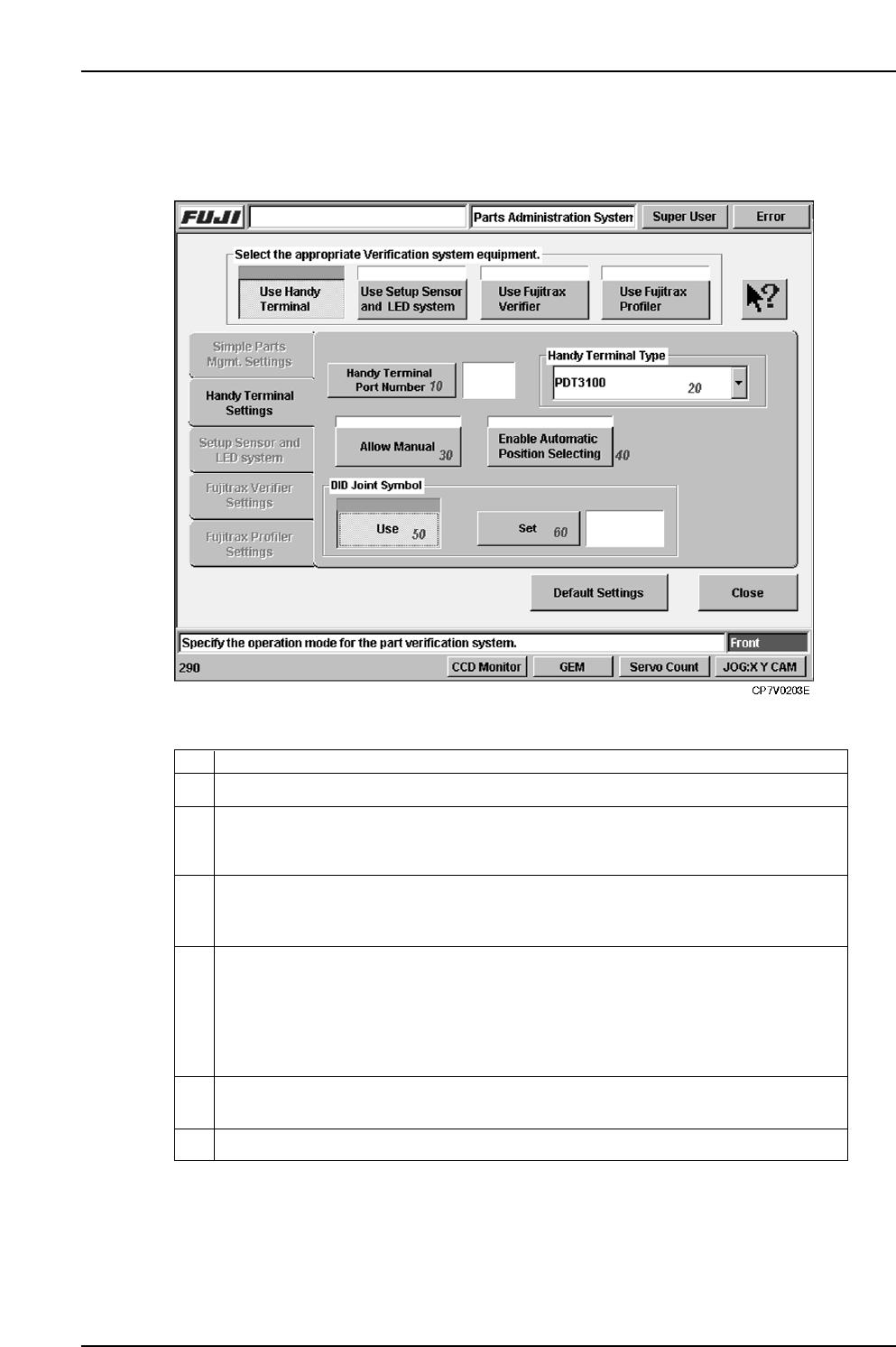
6.3 Handy Terminal Settings Tab
The setting items contained in the Handy Terminal settings tab are described below.
10 Specifies the communication port number to which Handy Terminal is to be connected.
Specifies the Handy Terminal type. Either a Scanner or PDT3100 type can be
selected. Before specifying this setting, check the Handy Terminal in question to
verify its type.
20
This function is used to omit the barcode read operation in the case where it is not
possible to read the using the Handy Terminal, or when feeders or parts are used that
are not administered by Fujitrax Verifier. Select to enable.
In the case where the device comment is included in the DID, specify the DID joint
symbol code to extract the device comment.
30
Specify whether to manually input the position of the device or to automatically set
when a device check is being performed using the Handy Terminal. Select to
automatically set the device positions in ascending order without requiring manual
input by the operator. Deselect when using manual input by the operator. This setting
can also be made at the PDT3100 environment settings when the PDT3100 is being
used.
40
50
60
Use this setting to specify the DID joint symbol.
ExplanationNo.
VT005Eb
6. Settings
Edition 2.0 29 CP-7-series Verification System Instruction Manual
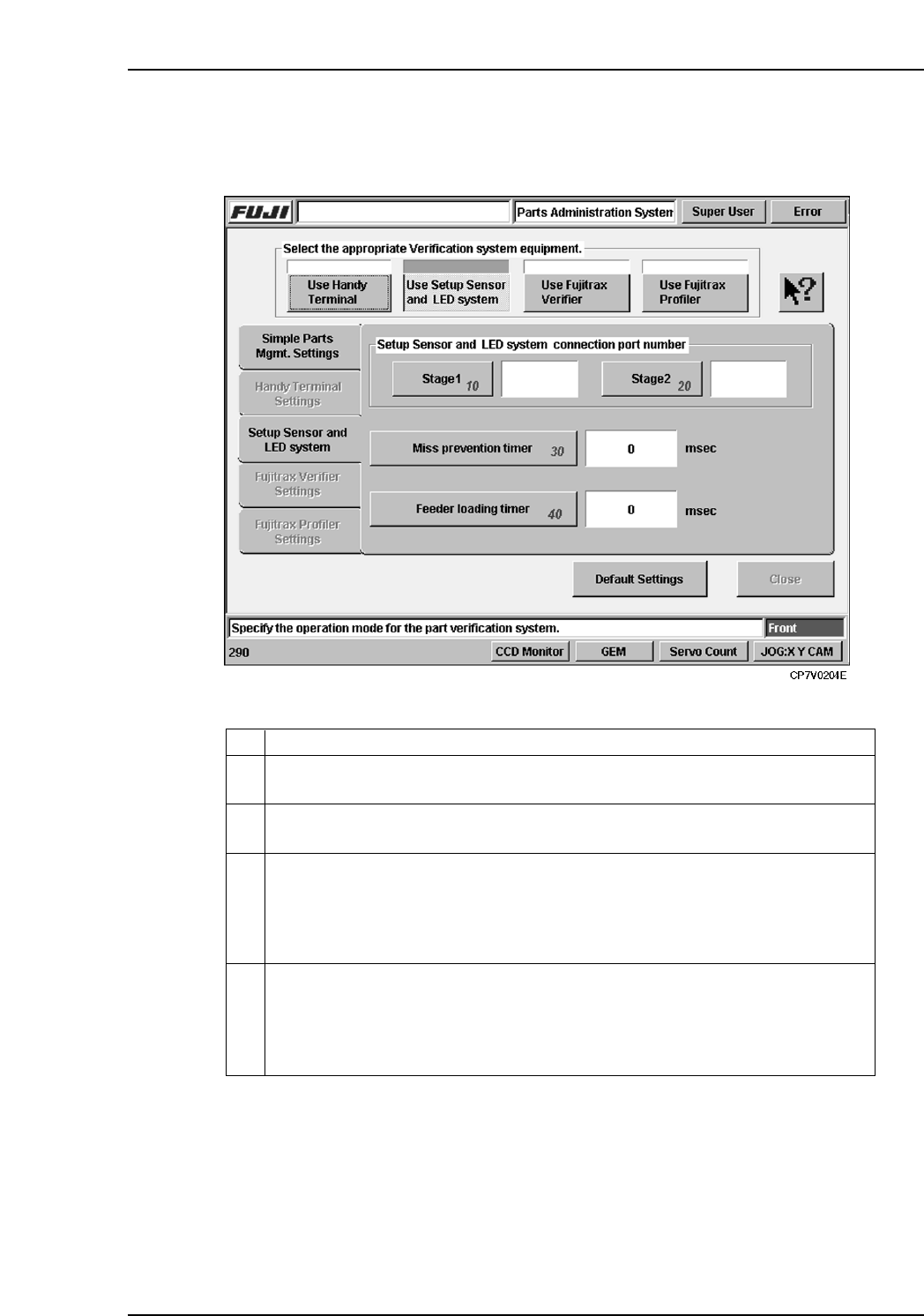
6.4 Setup Sensor & LED System Settings Tab
The setting items contained in the [Setup Sensor & LED System] tab are described below.
10 Specifies the communication port to which the Stage 1 setup sensor & LED
sequencer is to be connected.
Specifies the communication port to which the Stage 2 setup sensor & LED
sequencer is to be connected.
20
There may be cases in which several attempts are required in order to properly set
a feeder on the table. Because the feeder mount/demount sensor detects each of
these attempts, there could be cases when an incomplete verification status occurs
even though a normal verification has been executed. To prevent such problems,
feeder mounts and demounts which occur during this timer period are not recognized.
30
This is the timer used in normal verification operations which employ the Handy
Terminal. The machine monitors the time period from the point when a reel barcode
is read by the Handy Terminal, until the point when the feeder is set on the table.
If this timer period is exceeded, an incomplete verification status occurs because
the operator may have set a different feeder on the table.
40
ExplanationNo.
VT006E
6. Settings
Edition 2.0 30 CP-7-series Verification System Instruction Manual
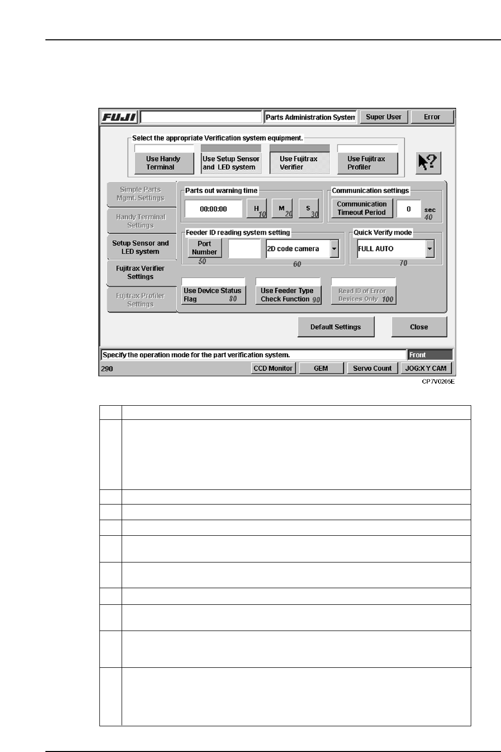
6.5 Fujitrax Verifier Settings Tab
The setting items contained in the [Fujitrax Verifier Settings] tab are described below.
10
Specifies the time for issuing a parts-out warning to the operator. The system
estimates when a given reel will run out of parts based on the reel s remaining parts
count, the number of parts used in that recipe, and the amount of time required to
place parts on a single board during production. The time specified by this setting
determines how many minutes prior to an estimated parts-out condition
Fujitrax Verifier is to issue the parts-out warning.
Specifies the minutes time for a parts-out warning.20
Specifies the communication port number to which the feeder ID read system is
connected.
40
Specifies the time-out period which applies to communications with Fujitrax Verifier.
50
80
This function determines whether the previously registered feeder status (stored in
Fujitrax Verifier) is reflected at the machine when reading feeder IDs.
70
Specify the Quick Verify mode from a choice of Standard , DC Auto or Full Auto .
ExplanationNo.
Specifies the seconds time for a parts-out warning.
30
60
Select the ID reading system from the drop down menu. A barcode and 2D code
camera selection is available.
90 This function is used to compare the tape width and pitch information etc. gathered
when reading the feeder ID and compare it with the data registered in the production
program.
In the case where only the Fujitrax Verifier option is used, it is not possible to
determine the load status of feeders, therefore a feeder check is performed upon the
start of auto operation.
When using this function, subsequent reading of the feeder ID is not performed for
those feeders for which an error has not occurred.
100
VT007Eb