CP-7-series Verification System Instruction manual(2.0E).pdf - 第127页
15. Explanation of Operation Screens Edition 2.0 116 CP-7-series V erification System Instruction Manual 15.3 Feeder ID Reading T est Screen Function This screen is used to perform a test r eading of the 2D code which is…
15. Explanation of Operation Screens
Edition 2.0 115 CP-7-series Verification System Instruction Manual
Screen Explanation
10
Indicates the current Stage number.
Display area for all slots.
Indicates the feeder ID reading status for all slots of one Stage.
Green
Yellow
Red
: Reading completed.
: Reading is enabled, but has not yet occurred.
: Reading is disabled (feeder not set, etc.).
Green : Indicates that reading is completed. The feeder ID where reading
occurred is indicated on the button.
Yellow : Reading is enabled, but has not yet occurred.
Red : Reading is disabled (feeder not set, etc.).
20
Indicates which part of the all slots display area is being displayed at the details
display area.
30
ExplanationNo.
50
Changes the display subject Stage.
60
Selects all slots where reading is to occur.
70
Changes to the screen for 2D camera adjustments.
Displays only when the 2D code feeder camera is used.
Returns to the [Main] screen.
90
40
Details display area.
Displays details about slot numbers and feeder ID reading statuses. When the
yellow button is pressed, it begins blinking, indicating that feeder ID reading is to
occur for that slot. The blinking stops when the button is pressed again.
VT014Eb
Enables the feeder ID reading [START] switch. This button is only enabled if reading
is to occur at one or more slots.
80
15. Explanation of Operation Screens
Edition 2.0 116 CP-7-series Verification System Instruction Manual
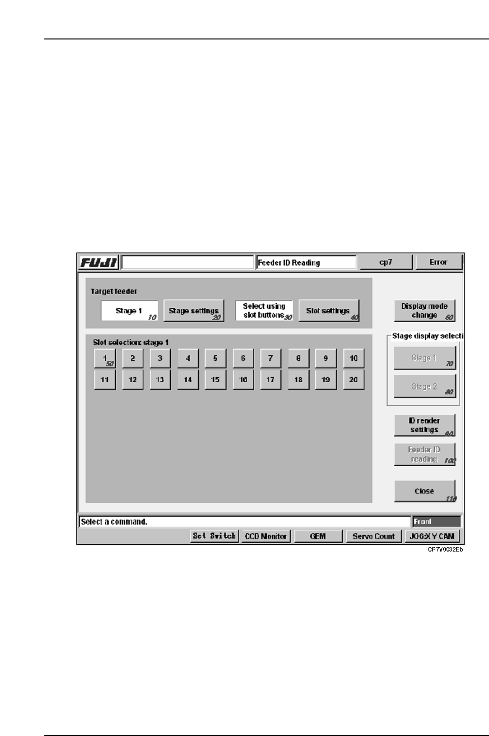
15.3 Feeder ID Reading Test Screen
Function
This screen is used to perform a test reading of the 2D code which is affixed to the feeder. As
this reading is only for test purposes, the reading results are lost when this screen is closed,
and those results are not used for part verification.
Input
• Execute the [Maintenance] - [Maintenance for Each Machine] - [Feeder Check Read Test]
commands to display the test screen:
• The [Feeder Check Reader Test] item displays at the [Maintenance]
- [Maintenance for Each Machine] - [Feeder Check Read Test] screen only if the
[Use Fujitrax Verifier] button is selected at the [Parts Administration System] screen.
Screen Access
15. Explanation of Operation Screens
Edition 2.0 117 CP-7-series Verification System Instruction Manual
Screen Explanation
10
Indicates the Stage where barcode reading is to occur.
20
Switches the Stage where barcode reading is to occur.
Indicates whether reading is to occur at all slots or at selected slots .
30
ExplanationNo
60
Selects the reading results display mode.
70
Selects the Stage for which results are to be displayed.
80
Selects the Stage for which results are to be displayed.
110
Returns to the [Maintenance] screen.
40
Switches between an all slots and selected slots status with regard to slots where
reading is to occur.
50
Used to select the desired slots when a selected slots status is specified with
regard to slots where reading is to occur.
VT016Ea
After selecting the stage and slots where reading is to occur, this button is pressed
to enable the START button.
100
90
Pushing this button displays the screen for adjusting the feeder ID read system.