CP-7-series Verification System Instruction manual(2.0E).pdf - 第81页
10. Using the DC AUTO Mode Edition 2.0 70 CP-7-series V erification System Instruction Manual 10.4.2.1 Device Check Start • A device check can be started in the following three ways. I. By selecting [Device Check] at the…
10. Using the DC AUTO Mode
Edition 2.0 69 CP-7-series Verification System Instruction Manual
10..4.1.5 Check Against Fujitrax Verifier Database
• The feeder/reel combination data read by the Fujitrax Verifier is checked against
the feeder/reel combination data in the Fujitrax Verifier database to see if it
matches.
• “Remaining parts count” information for each reel is downloaded from Fujitrax
Verifier.
10.4.1.6 Production Start
• Production is started automatically.
10.4.1.7 Part Supply
• Parts are supplied.
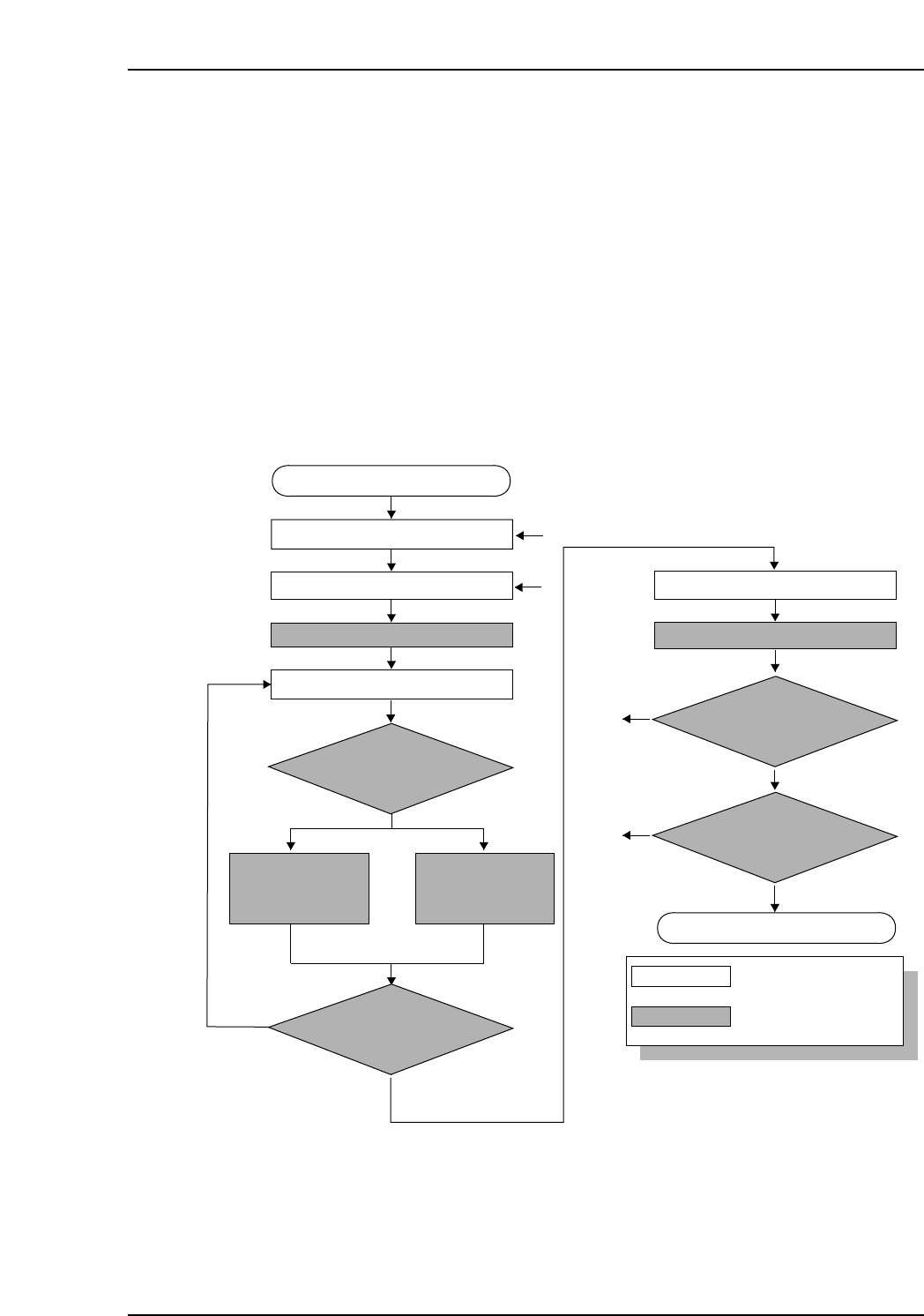
10.4.2 Device Check Flowchart
Device check start
Stage to be checked is determined
Slot to be checked is determined
Mismtch
No
No
No
To [1]
To [2]
Match
DID reading
ID which was acquired
is compared with recipe’s
device comment
Is a device
comment delimiter being used
in the DID?
: Operator tasks
: Machine processing
LED on at slot to be verified
Device comment is
extracted from the
DID.
Device comment is
obtained from the
Verifier, based on the
DID.
Feeder is set
LED on at stage to be verified
Unshaded box
Shaded box
[1]
[2]
Yes
Yes
Yes
Device check completed
All device checks completed
at this stage?
Device checks completed
at both sides?
10. Using the DC AUTO Mode
Edition 2.0 70 CP-7-series Verification System Instruction Manual
10.4.2.1 Device Check Start
• A device check can be started in the following three ways.
I. By selecting [Device Check] at the machine control panel.
II. At the PDT-3100 [Main Menu], select [1. Verify Check], then press [Enter].
PDT-3100’s Main Menu
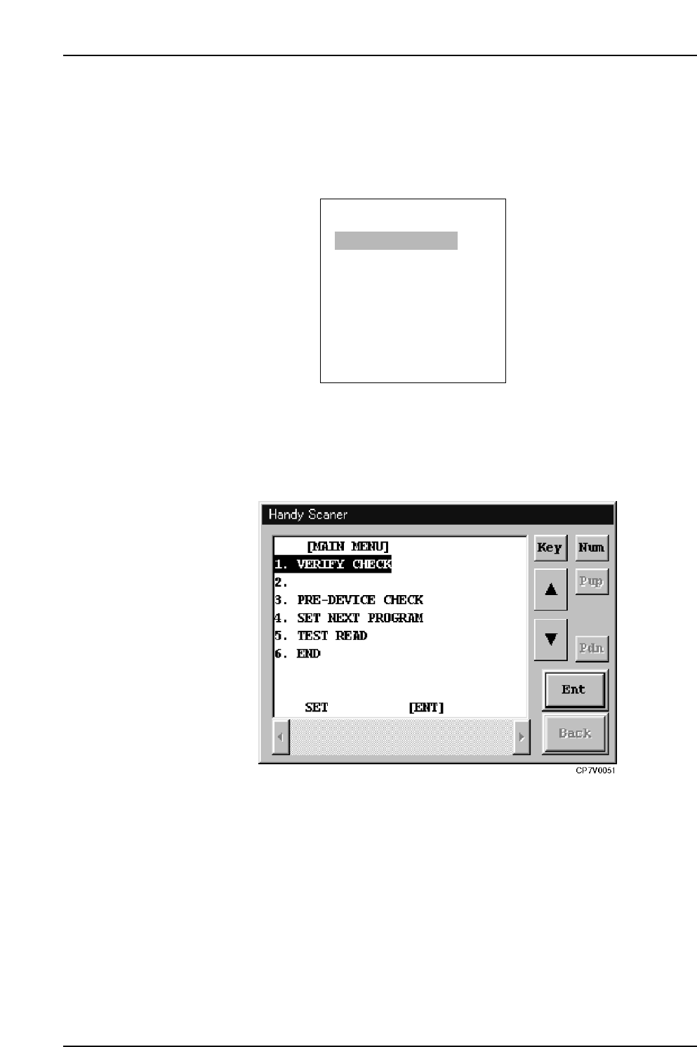
III. With the main menu displayed at the Handy Scanner dialog box, read the "1"
barcode, and select "1. VERIFY CHECK".
Handy Scanner’s Main Menu
ENTER
[MAIN MENU]
1. VERIFY CHECK
2. PRE VERIFY CHECK
3. SET VERIFY RECIPE
4. PALLET SUPPLY
5. TEST READ
SELECT NO.=v
▼▲
CP7V0005
10. Using the DC AUTO Mode
Edition 2.0 71 CP-7-series Verification System Instruction Manual
10.4.2.2 Determining the Stage to be Verified
• The stage to be verified can be determined in the following four ways.
I. If a feeder is set in the slot where an LED is on, the stage to be verified can
be determined by removing that feeder (the slot to be verified is also
determined at this time).
II. The stage number barcode affixed to the machine rear can be read to the
PDT-3100.
III. The stage to be verified can be selected from the stage selection screen at the
PDT-3100.
PDT-3100’s Stage Selection Screen
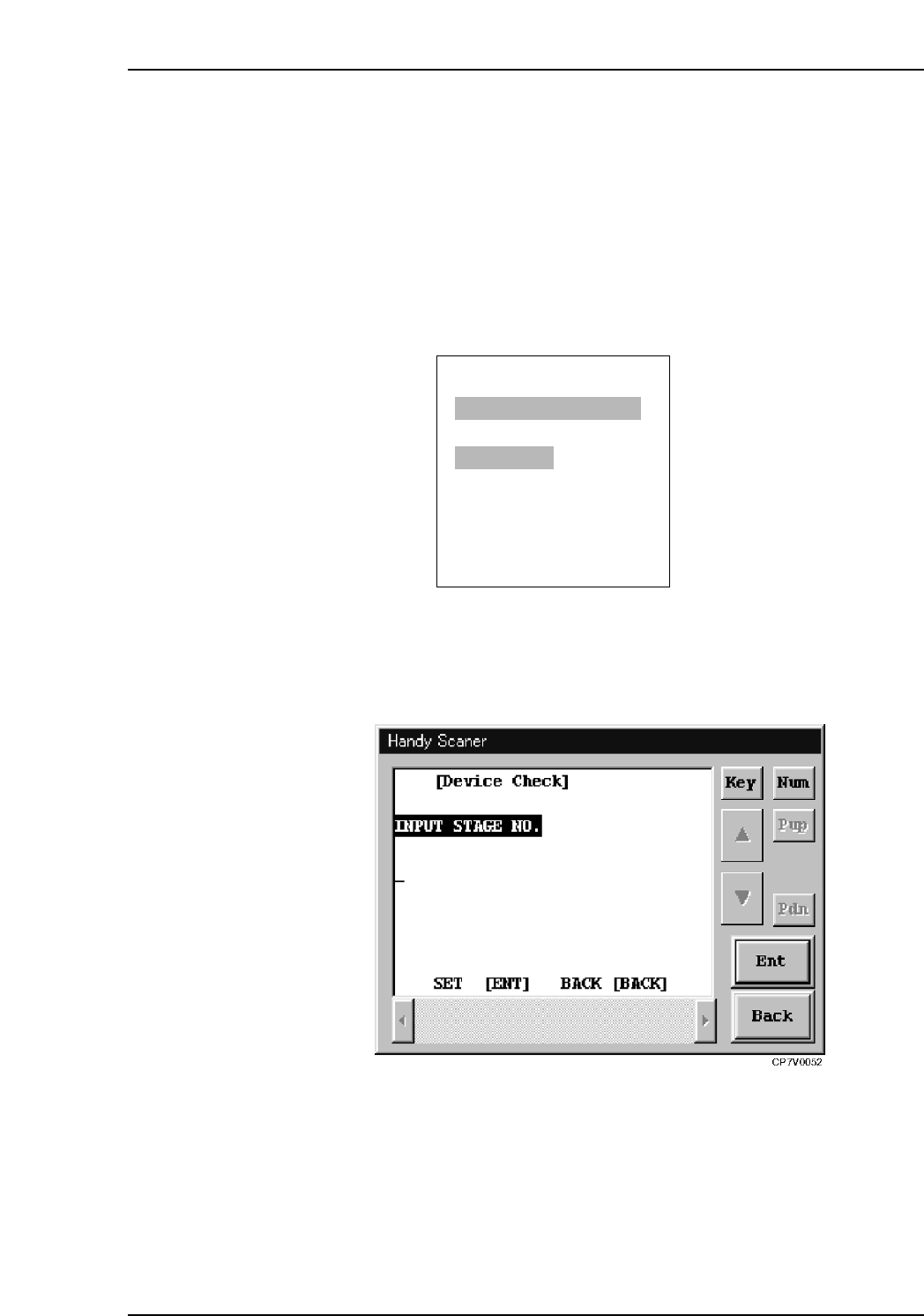
IV. With the “Input Stage No.” item displayed at the Handy Scanner dialog box,
use the scanner to read the Stage number barcode affixed on the machine
rear.
Handy Scanner’s Stage Selection Screen
Notes:
• The Verification operation must be performed for each stage.
• To perform a verification at Stage 2, for example, after Stage 1 has been selected, the
device check must be interrupted, and the verification must be started again.
• When using the Scanner, it is possible to return to the “Input Stage No.” step without
interrupting the device check. This is done by reading the “BACK” barcode.
ENTER/QUIT:
[VERIFY CHECK]
CP7V0006a
▲
SELECT START STAGE
1. STAGE1
2. STAGE2
SELECT STAGE NO.=v
▼▲