CP-7-series Verification System Instruction manual(2.0E).pdf - 第71页
9. Using The Normal V erification Mode Edition 2.0 60 CP-7-series V erification System Instruction Manual 9.6.2.3 Determining the Slot to be V erified • If the stage to be verified was determined by removing a feeder , t…
9. Using The Normal Verification Mode
Edition 2.0 59 CP-7-series Verification System Instruction Manual
9.6.2.2 Determining the Stage to be Verified
• The stage to be verified can be determined in the following four ways.
I. If a feeder is set in the slot where an LED is on, the stage to be verified can
be determined by removing that feeder (the slot to be verified is also
determined at this time).
II. The stage number barcode affixed to the machine rear can be read to the
PDT-3100.
III. The stage to be verified can be selected from the stage selection screen at the
PDT-3100.
PDT-3100’s Stage Selection Screen
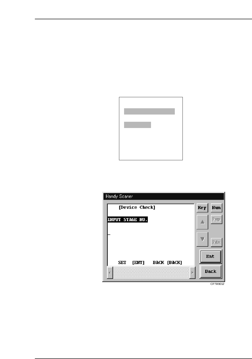
IV. With the “Input Stage No.” item displayed at the Handy Scanner dialog box,
use the scanner to read the Stage number barcode on the rear of the machine.
Handy Scanner’s Stage Selection Screen
Notes:
• The Verification operation must be performed for each stage.
• To perform a verification at Stage 2, for example, after Stage 1 has been selected, the
device check must be interrupted, and the verification must be started again.
• When using the Scanner, it is possible to return to the “Input Stage No.” step without
interrupting the device check. This is done by reading the “BACK” barcode.
ENTER/QUIT:
[VERIFY CHECK]
CP7V0006a
▲
SELECT START STAGE
1. STAGE1
2. STAGE2
SELECT STAGE NO.=v
▼▲
9. Using The Normal Verification Mode
Edition 2.0 60 CP-7-series Verification System Instruction Manual
9.6.2.3 Determining the Slot to be Verified
• If the stage to be verified was determined by removing a feeder, this step can be
skipped because the slot to be verified will also have been determined at that time.
• The slot to be verified can be determined in following three ways.
I. If a feeder is set in a slot where an LED is on at the verify subject stage, that
slot will become a verify subject if that feeder is removed.
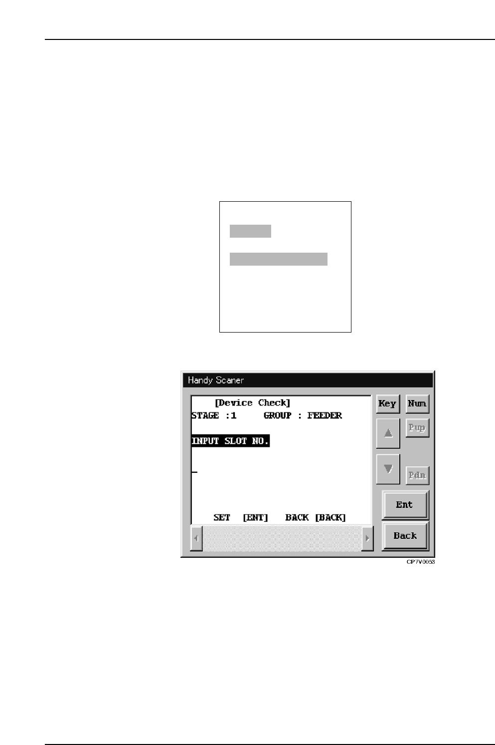
II. By using the Handy Terminal to read the slot number barcodes affixed to
each slot.
III. By keying in the slot number from the PDT-3100’s numeric key pad.
PDT-3100’s Slot ID Reading Command Screen
Handy Scanner’s Slot ID Reading Command Screen
9.6.2.4 LED ON at Slot to be Verified
• Only the LED at the slot to be verified is on.
• When subsequently setting feeders, the LEDs indicate which positions those
feeders should be set in.
ENTER/QUIT:
[VERIFY CHECK]
CP7V0007a
▲
STAGE1
READ SLOT ID LABEL
SLOT ID=v
9. Using The Normal Verification Mode
Edition 2.0 61 CP-7-series Verification System Instruction Manual
9.6.2.5 DID Reading
• DID data can be read in the following two ways.
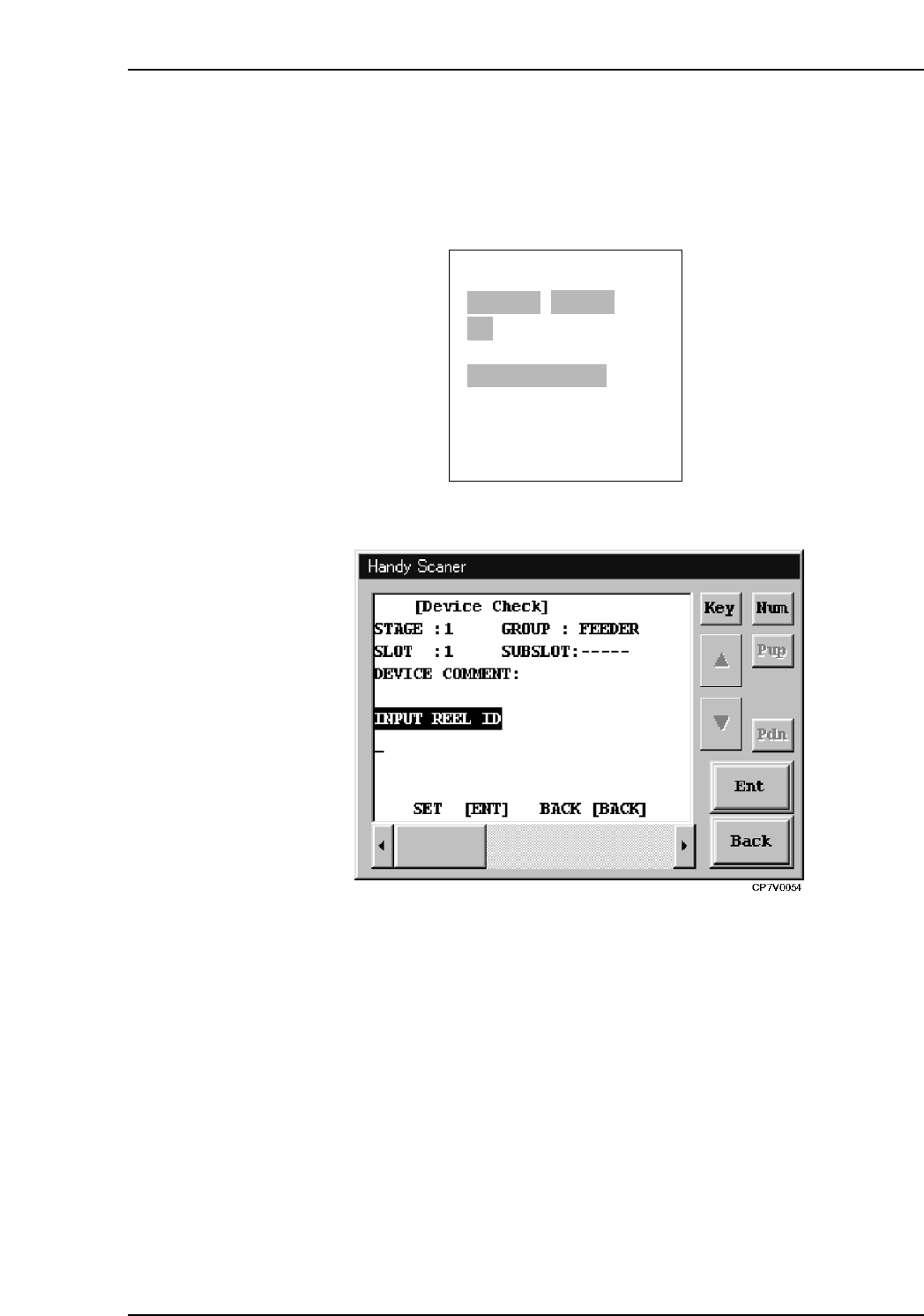
I. The DID barcode attached to the reel can be read to the Handy Terminal.
II. The DID can be entered using the PDT-3100’s alphabetic and numeric keys.
PDT-3100’s DID reading command screen
Handy Scanner’s DID Reading Command Screen
9.6.2.6 Extracting a Device Comment from the DID
• A DID Joint Symbol is used within the DID so that the device comment can be
extracted from the DID character string.
ENTER/QUIT:
[VERIFY CHECK]
CP7V0012a
▲
STAGE1 SLOT ID:1
ST:PARTS END
READ DID LABEL
DID=v