CP-7-series Verification System Instruction manual(2.0E).pdf - 第20页
4. Adjustments Edition 2.0 9 CP-7-series V erification System Instruction Manual 4.3 Feeder ID Reading System Adjustment 1. Adjustment Method For 2D Code Camera Note: The 1~4 procedure steps below are settings to enable …
4. Adjustments
Edition 2.0 8 CP-7-series Verification System Instruction Manual
4.2 Setup Sensor & LED Adjustment
1. Select the following commands: [Maintenance] - [Configuration]
- [Machine Function Settings] - [Part Administration System]
- [Use Setup Sensor and LED System] at the machine’s touch screen.
2. Select the [Maintenance] - [I/O Check] commands to display the monitoring system’s
[Stage 1] and [Stage 2] buttons.
Turn the I/O output signals on at the first and last slots of each stage (slot Nos. 1 and 30,
or 1 and 40 on the CP-742ME and, 1 and 70 on the CP-742E) to turn the LEDs ON.
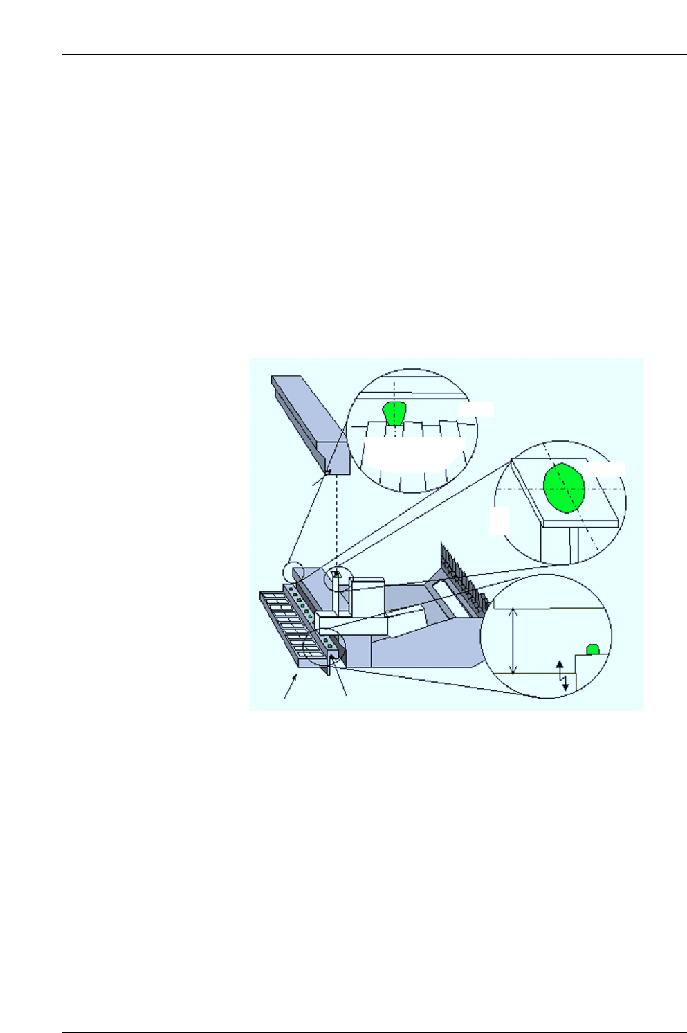
Adjust the positions of the feeder removal position LED and the feeder set position LED
so that they are aligned with the feeder lever and feeder pallet slot centers as shown in
the figure below.
Next, adjust the height until the distance between the sensor and feeder is 80 mm, then
set a feeder in position and use I/O commands to check the response.
Feeder removal
position LED
Sensor beam
Feeder pallet
Rear view
Feeder
lever
Feeder
80 mm
Sensor
Feeder set position LED
Setup sensor
CP7V0086E
Sensor beam
4. Adjustments
Edition 2.0 9 CP-7-series Verification System Instruction Manual
4.3 Feeder ID Reading System Adjustment
1. Adjustment Method For 2D Code Camera
Note: The 1~4 procedure steps below are settings to enable communication between the
application and the 2D camera controller. Once these controller settings have been
specified, they need not be specified again unless the controller is replaced.
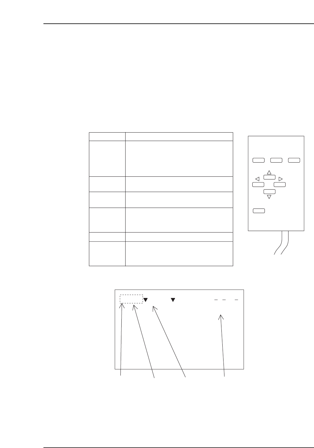
(1) Connect the auxiliary console to the 2D code camera controller. Connect a monitor to
the controller for those machines not equipped with a rear monitor.
• Console operation procedure
• Monitor screen display
Scene No.: This should be set to “Scene 1”.
Mode: The currently selected mode is indicated.
Displayed Image: Indicates the type of image which is currently displayed. The
“Freeze” mode displays the most recent 24 images (0 ~ 23)
which are always saved. The “Through” mode displays the
real (live) image. Switch between the “Freeze” and “Through”
modes by pressing [SHIFT]+[▼] or [SHIFT]+[▲].
CP7V0088E
Scene 0 System
Cursor Scene No. Mode Displayed image
—ms
ESC TRIG
SHIFT
ENT
Key Operation
At hierarchical menu screens, pressing
this key moves 1 level upward. At setting
screens, pressing this key aborts a
setting operation and returns 1 level
upward.
ESC
Executes a reading operation.
(Press 1 time = 1 reading operation.)
TRIG
Registers the selected function or setting
value.
ENT
These keys move the cursor up and down.
They are also used when entering numeric
setting values (increase/decrease).
UP/DOWN
These keys move the cursor left and right.LEFT/RIGHT
This key has no function when pressed by
itself. It functions only when pressed
together with another key.
SHIFT
CP7V0087E
Console
4. Adjustments
Edition 2.0 10 CP-7-series Verification System Instruction Manual
(2) With a “Scene 1” status established, press the [→] key at the console to move to the
mode item, then set the [System] content as shown in Table 1.
(3) After setting all the [System] items, move to the [Save] item to save the data.
(4) Proceed to the [Measure] item.
(5) At the machine’s touch-screen, select [Maintenance] - [Configuration]
- [Machine Function Settings] - [Part Administration System] - [Use FujiTrax Verifier],
then select [Fujitrax Verifier Settings], and select [2D code camera] at the “Feeder ID
reading system” item.
(6) Set a jig in slot 1 of Stage 1, then move to the pick-up position.
(7) Select [Maintenance] - [Maintenance for Each Machine] - [Feeder Check Reader Test]
- [Feeder ID Reading] to display a broken line on the monitor. As the “Through” screen
mode (real image) is in effect at this time, adjust the camera height until the jig is in
focus.
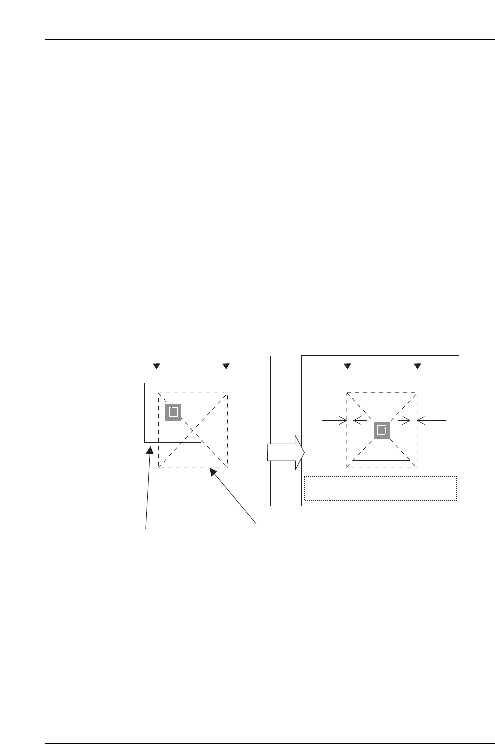
(8) Adjust the camera in the XY-directions to align the broken line center with the center of
the square label on the jig (the gap between the broken line frame and the label sides
should be uniform as shown below).
(9) Restart the machine and verify that no errors occur.
Scent 0
Measurement
Scent 0
Measurement
Gap
Gap should be uniform on all sides
Jig label
Monitor’s broken line display
Gap
CP7V0089E