CP-7-series Verification System Instruction manual(2.0E).pdf - 第65页
9. Using The Normal V erification Mode Edition 2.0 54 CP-7-series V erification System Instruction Manual 9.3.8 All LEDs ON at Stage to be V erified LEDs for all slots to be verified at the current verify subject stage a…

9. Using The Normal Verification Mode
Edition 2.0 53 CP-7-series Verification System Instruction Manual
9.3.7 Setting the Feeder
• Set a feeder in the slot to be verified (slot where LED is on).
• The system will not proceed to the next step until a feeder is set in the slot where
the LED is on.
* Note concerning the feeder set timer:
The purpose of this timer function is to prevent the wrong feeder (a feeder other than the one from
which the device comment was read) from being set in the verify target slot. After the device
comment is read, this function monitors the time which elapses until that feeder is set in the slot.
If a wrong feeder is set in the slot, additional time will have been required to ready that feeder, and
the time which elapses before the wrong feeder is set will therefore be longer than usual. If the
time required to set the feeder is longer than that specified by the feeder set timer, this indicates
that a wrong feeder was set.
If the feeder set timer function is not used, a feeder is simply set in the slot where the LED is on
without regard to the time which elapses, and that device is verified (“Parts Present” displays at
the device check screen).
If the feeder set timer function is used, and if the time which elapses before the feeder is set
exceeds the feeder set timer period, the Verification operation for that slot will end in error even if
the correct feeder was set in the slot (“Unchecked” displays at the device check screen). In this
case, the Verification operation must be performed again.
9. Using The Normal Verification Mode
Edition 2.0 54 CP-7-series Verification System Instruction Manual
9.3.8 All LEDs ON at Stage to be Verified
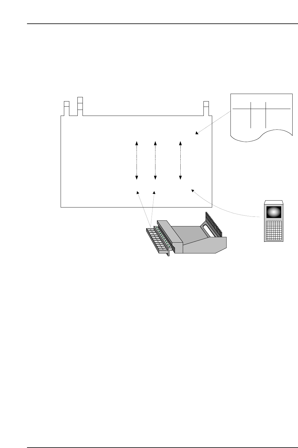
LEDs for all slots to be verified at the current verify subject stage are on.
Data flow
The position where the feeder was set and the device comment read by Handy Terminal
is checked against the recipe to determine if the data matches.
CC
CC
PP
PP
77
77
1 1 aaaaa
1 2 bbbbb
2 1 ccccc
2 2 ddddd
Stage Slot Comment DIDFIDL
Stage Slot Comment
CP7V0017E
Production Program
Specifications:
Acquired Data:
(4) Comparison
Stage
Slot
Comment
Production Program
(1) Production Program Analysis
(2) Device Comment Readings
(3) Feeder Settings
9. Using The Normal Verification Mode
Edition 2.0 55 CP-7-series Verification System Instruction Manual
9.4 Normal Verification Procedure 5
The normal verification mode is inoperative in this configuration because the Handy Terminal
is not used. Only the quick verification mode is operative.
For details concerning the quick verification procedure for this configuration, refer to the
“Quick Verification Procedure 1” section.
9.5 Normal Verification Procedure 7
The normal verification mode is inoperative in this configuration because the Handy Terminal
is not used. Only the quick verification mode is operative.
For details concerning the quick verification procedure for this configuration, refer to the
“Quick Verification Procedure 3” section.
9.6 Normal Verification Procedure 8
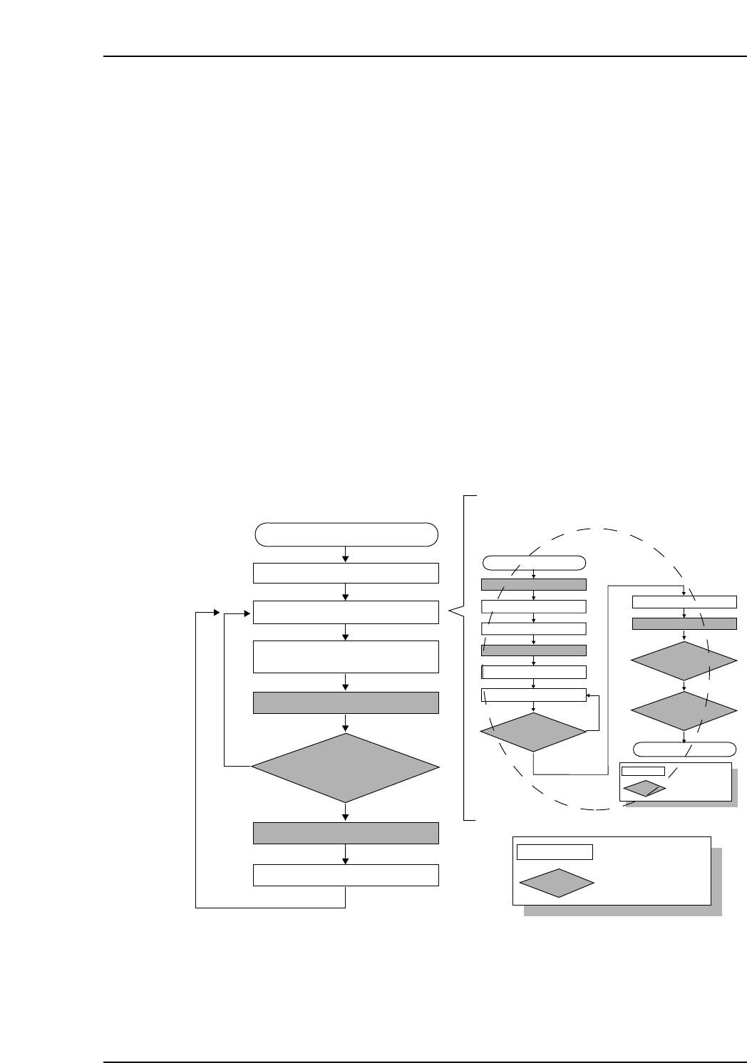
9.6.1 Operation Flowchart
When automatic operation begins following a device check, the feeder ID is read first,
then the feeder / reel combination information and other device information such as the
“remaining parts count”, etc., is downloaded from Fujitrax Verifier.
CP7V0011Ea
: Operator tasks
: Machine processing
Unshaded box
Shaded box
Device check start
Recipe switching
Device check
Part supply
Parts out occurrence
Automatic operation start
(START button pressed)
Mismatch
Checked against Verifier database
Feeder ID reading
Production start
The device check procedure is explained later
Match