CP-7-series Verification System Instruction manual(2.0E).pdf - 第78页
10. Using the DC AUTO Mode Edition 2.0 67 CP-7-series V erification System Instruction Manual 10. Using the DC AUTO Mode 10.1 Opration Conditions The DC AUTO mode is only operative when "Use Handy T erminal" an…
9. Using The Normal Verification Mode
Edition 2.0 66 CP-7-series Verification System Instruction Manual
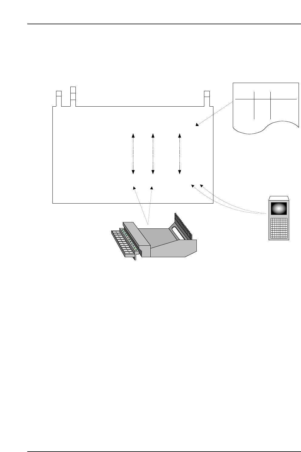
Data flow (after automatic operation start)
The FIDL which was read is used as a key to search the Fujitrax Verifier database in
order to download the required information.
CC
CC
PP
PP
77
77
1 1 aaaaa
1 2 bbbbb
2 1 ccccc
2 2 ddddd
Stage Slot Comment DIDFIDL
Stage Slot Comment
Production Program
Specifications:
Acquired Data:
(5) Comparison!
Stage
Slot
Comment
Production Program
(1) Production Program Analysis
(3) Device comment
reading
(2) DID Readings
(4) Feeder Settings

10. Using the DC AUTO Mode
Edition 2.0 67 CP-7-series Verification System Instruction Manual
10. Using the DC AUTO Mode
10.1 Opration Conditions
The DC AUTO mode is only operative when "Use Handy Terminal" and "Use Fujitrax Verifier"
settings are specified at the verification system settings.
10.2 Preparations
10.2.1 Settings
At the [Maintenance] - [Configuration] - [Machine Function Settings]
- [Parts Administration System] - [Fujitrax Verifier Setting] tab, specify the DC AUTO
Quick Verify mode. See Chapter 6 (Settings) for details.
Note: Both Fujitrax Verifier and Handy Terminal are used in the DC AUTO mode. Therefore, the
DC AUTO Quick Verify mode is only selectable when the "Use Handy Terminal" and "Use
Fujitrax Verifier" settings are specified.
10.3 DC AUTO Mode Operation Procedure
Verification operations vary somewhat, depending on the verification configuration (devices)
which are used. These devices can be selected at the [Select the appropriate Verification
system equipment] item on the [Parts Administration System] screen. The following buttons
are used to select the desired devices:
• [Use Handy Terminal]
• [Use Setup Sensor and LED system]
• [Use Fujitrax Verifier]
The table below shows the device combinations and corresponding procedures.
Configuration 6
✔ N/A ✔
Procedure 1
(Not supported)
Procedure 2
✔✔✔
Configuration 8
Use Handy Terminal
Button
Configuration
Use Setup Sensor
and LED system
Use Fujitrax Verifier
Procedure
10. Using the DC AUTO Mode
Edition 2.0 68 CP-7-series Verification System Instruction Manual
10.4 DC AUTO Mode Procedure 2
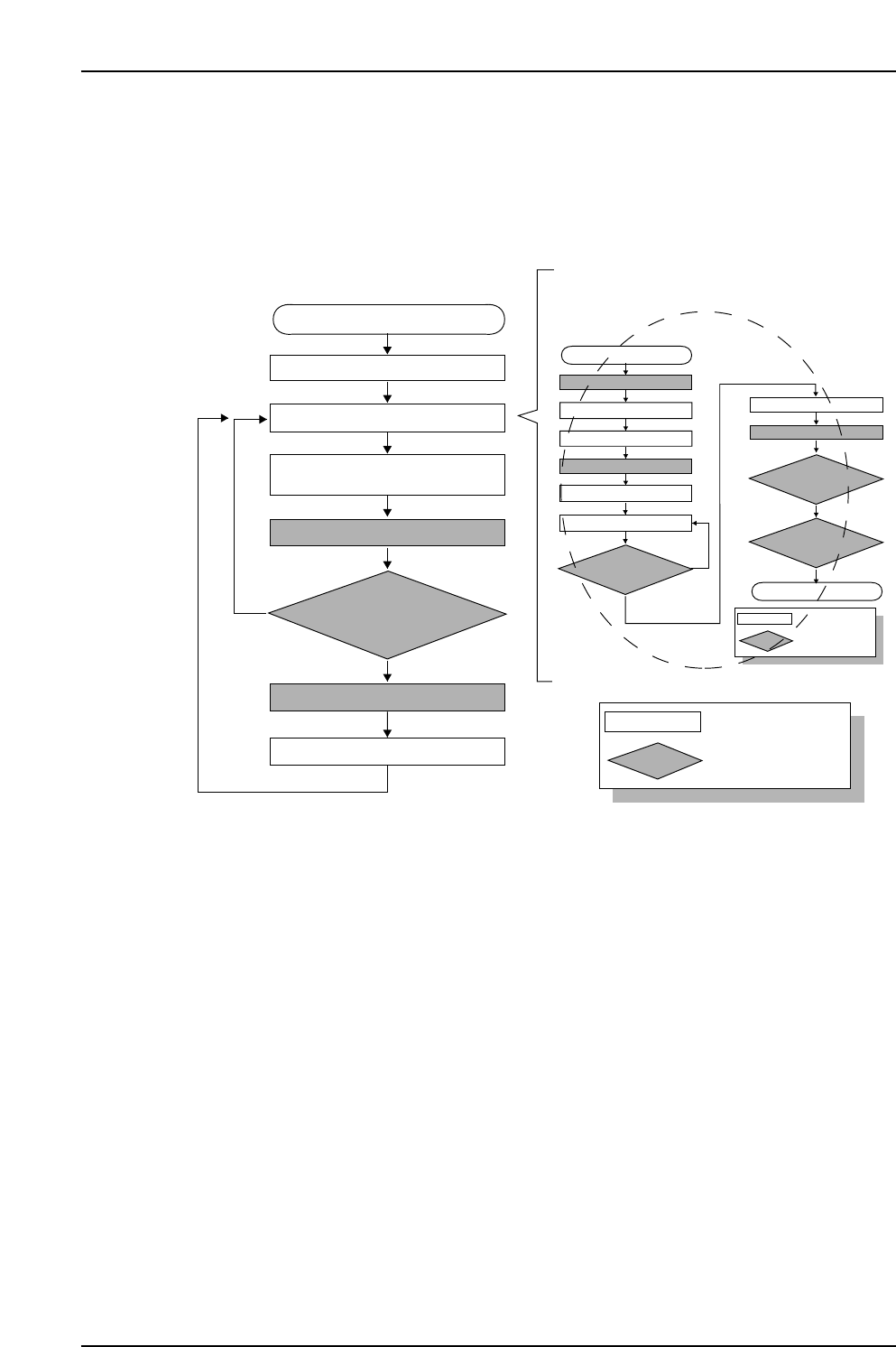
10.4.1 Operation Flowchart
When automatic operation begins following a device check, the feeder ID is read first,
then the feeder / reel combination information and other device information such as the
“remaining parts count”, etc., is downloaded from Fujitrax Verifier.
10.4.1.1 Recipe Switching
• The recipe is switched.
10.4.1.2 Device Check
• Device check is performed (see following pages for details).
• An “Unread FIDL” status displays at the device check screen after a device check is
completed for a slot.
• The “Unread FIDL” status changes to a “Parts Present” status following Fujitrax
Verifier verification at slots where feeder ID reading is completed without error.
10.4.1.3 Automatic Operation Start
• Automatic operation begins.
10.4.1.4 Feeder ID Reading
• The camera at ST1 reads the feeder IDs affixed to each feeder.
• Feeder ID reading occurs only at slots where an “Unread FIDL” status exists.
• The “Unread FIDL” status changes to a “Unread HOST” status at slots where
feeder ID reading is completed without error.
CP7V0011Ea
: Operator tasks
: Machine processing
Unshaded box
Shaded box
Device check start
Recipe switching
Device check
Part supply
Parts out occurrence
Automatic operation start
(START button pressed)
Mismatch
Checked against Verifier database
Feeder ID reading
Production start
The device check procedure is explained later
Match