CP-7-series Verification System Instruction manual(2.0E).pdf - 第17页
3. Hardware Configuration Edition 2.0 6 CP-7-series V erification System Instruction Manual 3.2.2 Device T able Area LED These LEDs provide the operator with an easy visual r eference for identifying slots where maintena…
3. Hardware Configuration
Edition 2.0 5 CP-7-series Verification System Instruction Manual
PDT-3100 Barcode for Resets
When an operator error is detected, an error message displays on the Handy Terminal
screen and a buzzer sounds. A buzzer also sounds on the machine. For example, if the
device comment read at the Handy Terminal is different from that specified by the
recipe, an error status occurs.
A verification error status can be reset by performing either one of the following two
ways:
1. By key input from the Handy Terminal.
2. By reading the reset barcode.
These reset methods cannot be used when an error occurs on the machine, or when
there is a communication error between the Handy Terminal and the machine.
PDT-3100 Barcode For Reading Stage Numbers
There are cases where the stage number must be specified in the course of a Verify
operation procedure.
This can be accomplished by reading the barcode.
Feeder ID Read System
There are two types of feeder ID read systems, one for barcodes and another for 2D
codes.
Handy Terminal Connector
This is the jack where the Handy Terminal is connected.
Scanner Barcode
These barcodes are used when a verification operation is being performed using the
scanner.
Barcode
MENU Displays at the [Main Menu] in the Handy Scanner dialog box.
BACK Returns to the previous Handy Scanner dialog box.
Clears the Handy Scanner dialog box from the screen.
RESET When setup sensors and LEDs are not being used, the slot in question
can be initialized to its "unchecked" status by reading the RESET
barcode at the device comment input screen.
ENT When a "Waiting for [ENT] input" status is in effect at the Handy Scanner
dialog box, read this ENT barcode to proceed to the next screen.
EXIT
STAGE 1
STAGE 2
Used to select a stage.
Explanation
SKIP When the automatic position selection function is in use, the subject slot
designation moves to the next slot when the SKIP barcode is read.
* When a SKIP is performed, only the subject slot is changed. A
verification must subsequently be performed for the skipped slot.
LOG-ON Not supported at present.
LOG-OFF Not supported at present.
1 ~ 12 Used to select an item which displays at the Handy Scanner dialog box.
At present, only 1~9 are used for Fujitrax-Verifier.
VT003Ea
3. Hardware Configuration
Edition 2.0 6 CP-7-series Verification System Instruction Manual
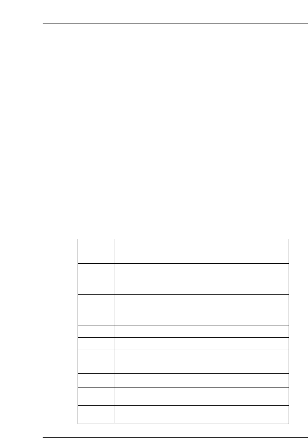
3.2.2 Device Table Area
LED
These LEDs provide the operator with an easy visual reference for identifying slots
where maintenance or check operations are required. The LEDs remain on at slots
where an error status exists.
When a device table is removed from its standby position, however, all of that table’s
LEDs switch off.
When a normal verification mode operation is performed using the Handy Terminal,
only the LED at the slot where the verification operation is to occur switches on, making
that slot easy to identify.
Setup Sensor
This sensor monitors the feeder mount/demount status at each slot. Monitoring is
enabled only when the device table is at the standby position.
Even if verification has been completed for a device, the verification must be performed
again if that device is demounted and then remounted. This prevents the wrong parts
from being mounted and used in production.
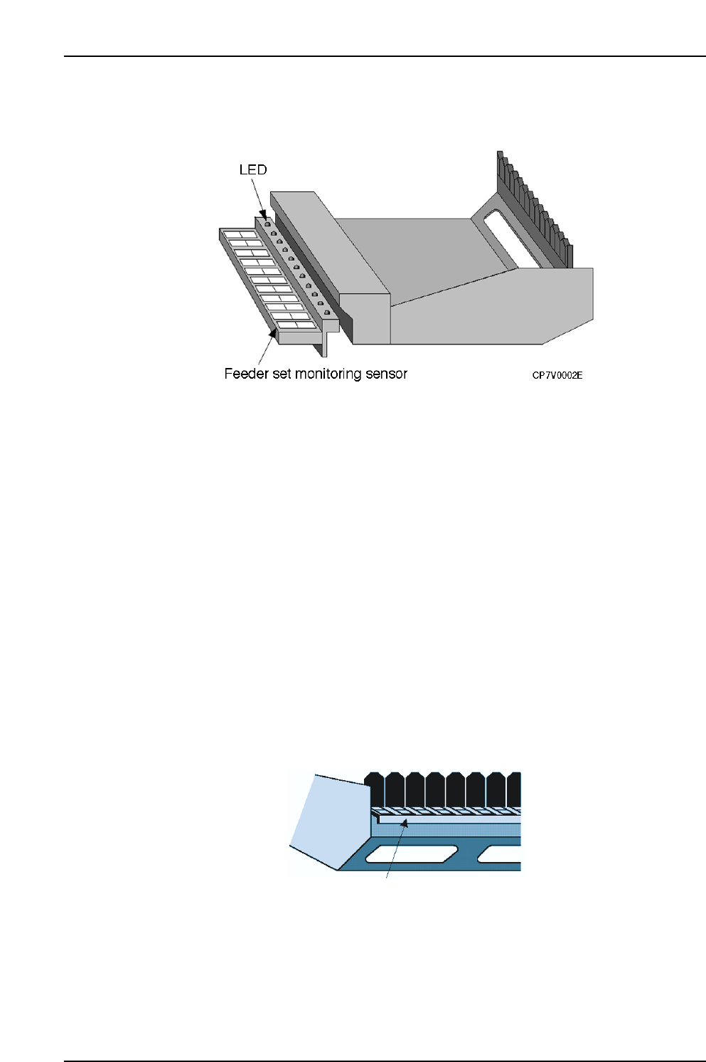
Barcode For Reading Slot Numbers
There are cases where a slot number must be specified in the course of the Verify
operation procedure. The specified slot can be determined by reading this barcode.
Barcode for reading
slot numbers
CP7V0003E

4. Adjustments
Edition 2.0 7 CP-7-series Verification System Instruction Manual
4. Adjustments
CAUTION
Check the D-axis calibration data before performing the
adjustments described below.
4.1 Handy Terminal Adjustment
This procedure consists only of a Handy Terminal operation check as no physical adjustments
are required. To perform the operation check, use a program with the same content as that
used on the CP-643E. The same verification barcodes are also used.
• For PDT3100
1. Select the following commands: [Maintenance] - [Configuration]
- [Machine Function Settings] - [Part Administration System] - [Use Handy Terminal] at
the machine’s touch screen.
2. Select the [Maintenance] - [Configuration] - [Machine Function Settings]
- [Part Administration System] - [Handy Terminal Settings], then select [PDT3100] as the
Handy Terminal type.
3. Turn the Handy Terminal power on.
4. Select the following commands to upgrade the Handy Terminal version: [Maintenance]
- [Maintenance for Each Machine] - [Version Up].
5. Using a production program, perform the device check function from the Handy
Terminal.
• For BL-N60
1. Select the following commands: [Maintenance] - [Configuration]
- [Machine Function Settings] - [Part Administration System] - [Use Handy Terminal] at
the machine’s touch screen.
2. Select the [Maintenance] - [Configuration] - [Machine Function Settings]
- [Part Administration System] - [Handy Terminal Settings], then select [Scanner] as the
Handy Terminal type.
3. Using a production program, perform the device check function from the Handy
Terminal.