CP-7-series Verification System Instruction manual(2.0E).pdf - 第24页
4. Adjustments Edition 2.0 13 CP-7-series V erification System Instruction Manual (3) Barcode r eader ’s laser beam adjustment a. At the machine’s touch-screen, use the [Stage No.] and [Slot No.] commands to specify Stag…
4. Adjustments
Edition 2.0 12 CP-7-series Verification System Instruction Manual
2. Adjustment Procedure For Barcode Reader
(1) Select the “Barcode reader” Setting
Begin by moving Stage 1 to its standby position.
At the machine’s touch-screen, select [Maintenance] - [Configuration]
- [Machine Function Settings] - [Part Administration System] - [Use FujiTrax Verifier],
then select [Fujitrax Verifier Settings], and select [Barcode reader] at the “Feeder ID
reading system” item.
(2) Mount the barcode reader position adjustment jig.
Set the barcode reader positioning jig in slot 1 of Stage 1, then select [Maintenance]
- [Maintenance for Each Machine] - [Feeder Check Reader Test] - [Feeder ID Reading] at
the control panel.
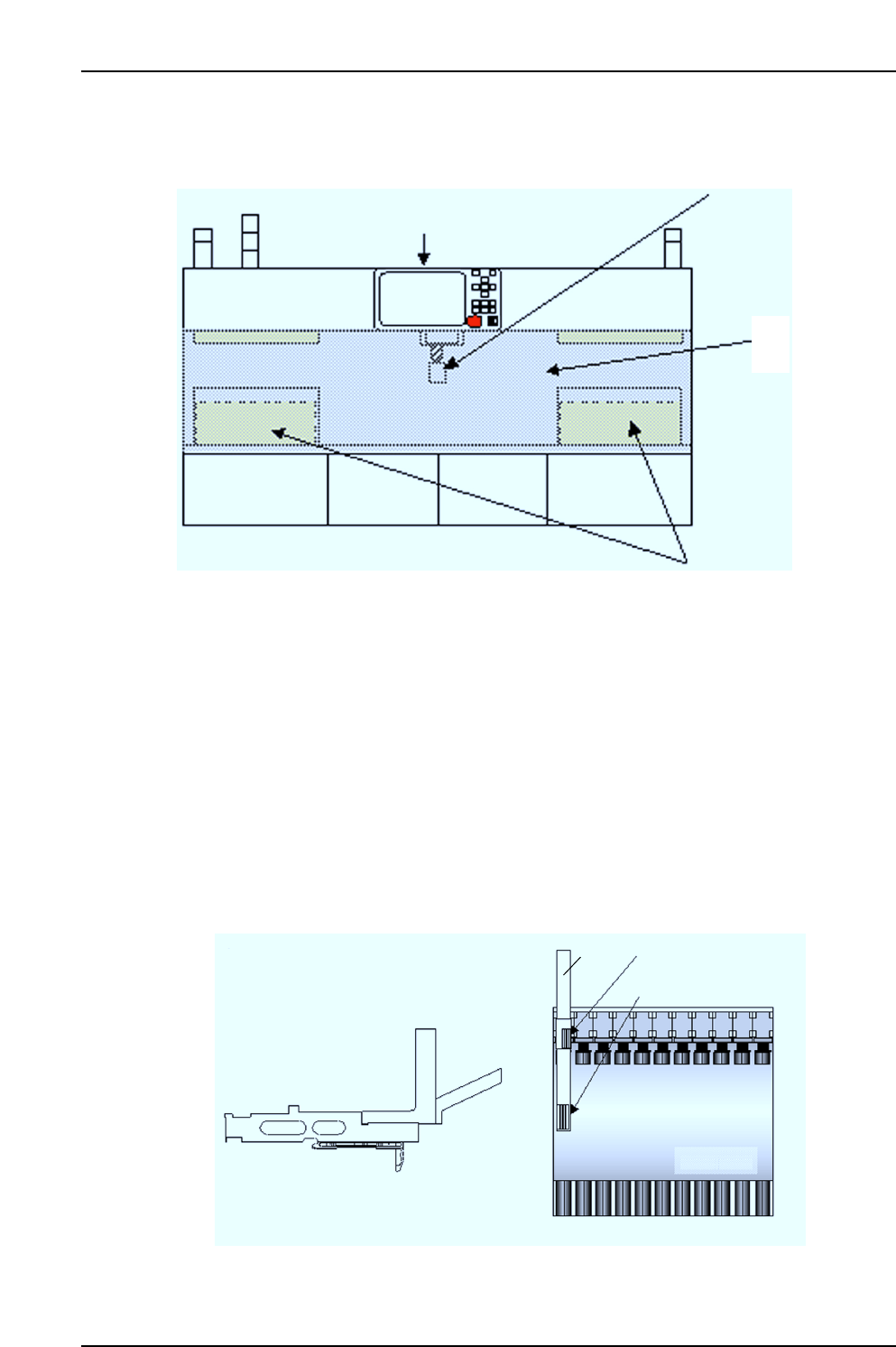
Z9726DCPJ1702
Z9726DCPJ1712
Z9528DHPJ2680
DCPJ0340
AWCC4602
Set jig in slot 1 of Stage 1
Jig
Stage 1
Positioning label 1
Positioning label 2
CP7V0091E
Feeder ID barcode reader position
adjustment jig components
Rear operation monitor
Barcode reader
mounting position
Device pallets
CP7V0093E
Acrylic cover
4. Adjustments
Edition 2.0 13 CP-7-series Verification System Instruction Manual
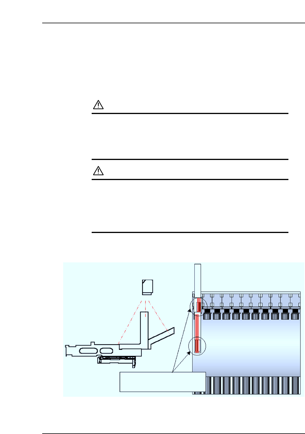
(3) Barcode reader’s laser beam adjustment
a. At the machine’s touch-screen, use the [Stage No.] and [Slot No.] commands to
specify Stage 1, Slot 1, then use the [D-Axis Position] command to move the jig to
the pickup position.
Next, select the [Laser On] command. If the laser beam is on, the “LASER ON”
LED lights on the top face of the barcode reader.
WARNING
To verify the “laser on” status, check the “LASER ON”
LED on the barcode reader’s top face. Never look directly
at the laser beam which is being emitted.
If the laser beam is directed at a reflective surface, use
care to prevent the beam from being reflected directly into
the eyes.
CAUTION
The machine’s rear center cover must be opened in order
to perform adjustments. Be sure that an emergency stop
status is established on the machine before opening the
cover. To ensure safe operation, press the [Emergency
Stop] button before beginning the procedure. The Laser
beam ON/OFF commands are enabled during an
emergency stop status.
b. Adjust the barcode reader position so that the center of the jig’s positioning label is
aligned with the center of the laser beam. Position adjustment is possible in the X-
and Q-directions.
Adjust the barcode reader position
so that the laser beam is at the
label center.
CP7V0092E
4. Adjustments
Edition 2.0 14 CP-7-series Verification System Instruction Manual
[Q-Direction Adjustment]
There are 2 positioning labels, and the barcode reader’s tilt angle (Q) is set by adjusting
the barcode reader position so that the center of the laser beam is centered between
positioning labels 1 and 2.
Note: When adjusting, use care to avoid over-loosening the barcode reader’s mounting bolts, as
this could cause the reader to come loose and fall, with the laser beam possibly being be
directed into the eyes.
(4) Feeder Barcode Reading Check
Remove the jig, then use two 7-inch feeders and two 13-inch feeders (with barcodes
affixed) to perform the check.
a. Set the 7-inch feeders in Slot 1 of Stage 1, and in the end slot of Stage 2 (Slot 30 on
CP-73, Slot 40 on CP-74M, Slot 70 on CP-74E). Set the 13-inch feeders in the end
slot of Stage 1, and in Slot 1 of Stage 2.
b. Select the [Maintenance] - [Maintenance for Each Machine]
- [Feeder Check Reader Test] - [Feeder ID Reading] commands at the machine’s
touch screen.
At the [Stage No.] and [Slot Settings] items, enter the stage and slot numbers where
the above feeders are set, then perform a test reading ([TEST READ]).
If reading is performed correctly, the barcode content (feeder ID) displays, and OK
displays as the reading result. Repeated reading tests should be performed.
If the reading results are OK, verify that the feeder IDs which were read match the
actual feeder IDs. Repeat this test 5 times, verifying that an OK result is obtained
each time. If 5 consecutive OK results are not obtained, readjust the barcode
reader’s position.
If the reading result is “FAIL”, this indicates that the barcode is either difficult to
read (low reading rate), or that it can’t be read at all. In this case, check the
following items.
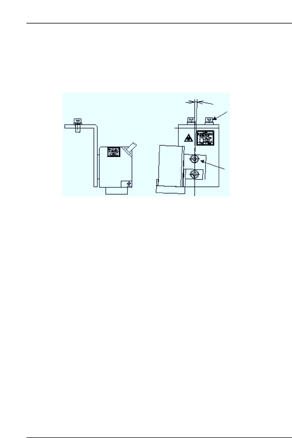
X-direction adjusting bolt
Side view Front view
2°
Q-direction adjusting bolt
CP7V0094E