CP-7-series Verification System Instruction manual(2.0E).pdf - 第32页
5. Explanation of Functions Edition 2.0 21 CP-7-series V erification System Instruction Manual 5.2.5 Reel Barcode Administration In the verification system, device comments must be affixed to the part r eel if Fujitrax V…
5. Explanation of Functions
Edition 2.0 20 CP-7-series Verification System Instruction Manual
5.2.4 Off-Machine Changeover
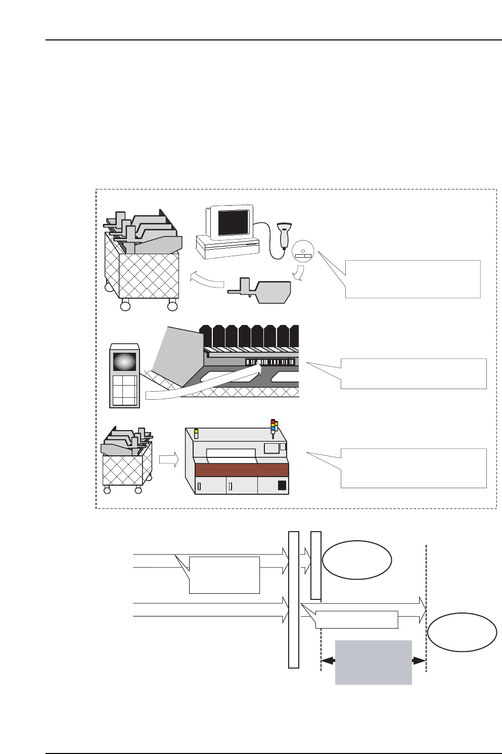
An “off-machine changeover” refers to the process in which an idle device table (or a
spare device table) is brought to the Fujitrax Verifier, and a feeder setup is then
performed.
As off-line changeover is performed away from the machine, it is even possible to, for
example, setup the spare table while performing auto operation in Joint mode.
Changeover time is minimized by simply loading the prepared spare table onto the
machine.
Verification is
performed using
Verifier
With off-line changeover
Without off-line changeover
Verification occurs
Production start
Production start
This changeover
time can be
eliminated by an
off-line changeover.
Changeover occurs
Pallet change
Verifier
Handy Scanner
(1) Verification is performed
using the Verifier during machine
production operation.
(2) Handy Terminal is used at the
machine to perform a changeover.
(3) A new pallet is set in position.
Another verification is not required
at the machine.
5. Explanation of Functions
Edition 2.0 21 CP-7-series Verification System Instruction Manual
5.2.5 Reel Barcode Administration
In the verification system, device comments must be affixed to the part reel if Fujitrax
Verifier is not used, whereas DID labels must be affixed if Fujitrax Verifier is used.
The device comment content differs from the DID content. Therefore, if Fujitrax Verifier
was being used, but has been disabled for some reason, the reel barcode must be re-
attached.
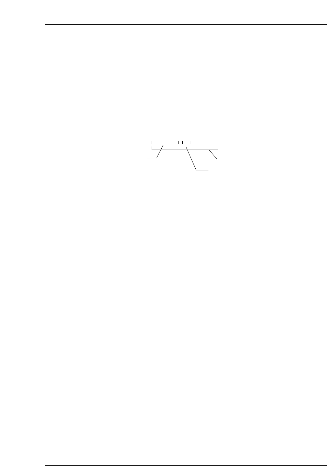
If the following DID character string format is used, however, a “DID Joint Symbol”
setting can simply be specified, eliminating the need to reattach the barcode labels.
Example of DID format
The first part of the above code is the device comment, with a hyphen (-) entered as the
“DID Joint Symbol”, followed by a serial number. The entire code is then handled as a
DID.
Creating DIDs with this format enables the device comment to be recognized as
“ABCDE” even if the barcode is read by the Handy Terminal.
A B C D E — 0 0 0 0 1
Device comment
DID Joint Symbol
DID
CP7V0036Ea

5. Explanation of Functions
Edition 2.0 22 CP-7-series Verification System Instruction Manual
5.3 Setup Sensor & LED Functions
5.3.1 LED Indicators
These LEDs provide the operator with an easy visual reference for identifying slots
where a verification operation is required, or is in progress.
When using a configuration which lacks this LED function, the operator must constantly
refer to the device check screen (or to the Handy Terminal screen) to identify the slots
which require a verification operation, and to identify the slots which require feeders.
The LEDs, on the other hand, allow these slots to be quickly and easily identified by eye.
5.3.2 Feeder Loading and Removal
This function monitors the feeder loading and removal operations when the device table
is in the retract position. For example, if a feeder where a device check has been
completed is removed and then loaded again, the status of that device will change in the
following sequence: [Parts present] - [Feeder absent] - [Unchecked].
Therefore, even if the wrong feeder has been loaded, that feeder will not be used in
production, provided that the device in question has been subjected to verification by
Handy Terminal or Fujitrax Verifier. This eliminates the risk of wrong parts being
placed due to human error.
Because the power supply for the unit which monitors the feeder mount/demount
status is independent of the machine power supply, monitoring of the feeder status
continues even when the device table is retracted and the machine power is OFF.