CP-7-series Verification System Instruction manual(2.0E).pdf - 第39页
6. Settings Edition 2.0 28 CP-7-series V erification System Instruction Manual 6.3 Handy T erminal Settings T ab The setting items contained in the Handy T erminal settings tab are described below . 10 Specifies the comm…
6. Settings
Edition 2.0 27 CP-7-series Verification System Instruction Manual
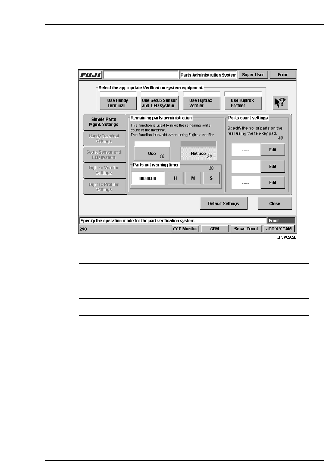
6.2 Simple Parts Management Settings Tab
The settings contained in the [Simple Parts Mgmt. Settings] tab are described below.
10
Enables the Remaining parts administration function. This function cannot be used
when using Fujitrax Verifier.
Disables the Remaining parts administration function.20
Make this setting in hours, minutes, and seconds to issue a warning prior to parts
running out.
30
Use this function to manually specify the number of parts left on the reel.
40
ExplanationNo.
VT020E
6. Settings
Edition 2.0 28 CP-7-series Verification System Instruction Manual
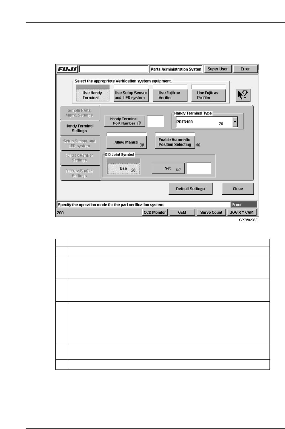
6.3 Handy Terminal Settings Tab
The setting items contained in the Handy Terminal settings tab are described below.
10 Specifies the communication port number to which Handy Terminal is to be connected.
Specifies the Handy Terminal type. Either a Scanner or PDT3100 type can be
selected. Before specifying this setting, check the Handy Terminal in question to
verify its type.
20
This function is used to omit the barcode read operation in the case where it is not
possible to read the using the Handy Terminal, or when feeders or parts are used that
are not administered by Fujitrax Verifier. Select to enable.
In the case where the device comment is included in the DID, specify the DID joint
symbol code to extract the device comment.
30
Specify whether to manually input the position of the device or to automatically set
when a device check is being performed using the Handy Terminal. Select to
automatically set the device positions in ascending order without requiring manual
input by the operator. Deselect when using manual input by the operator. This setting
can also be made at the PDT3100 environment settings when the PDT3100 is being
used.
40
50
60
Use this setting to specify the DID joint symbol.
ExplanationNo.
VT005Eb
6. Settings
Edition 2.0 29 CP-7-series Verification System Instruction Manual
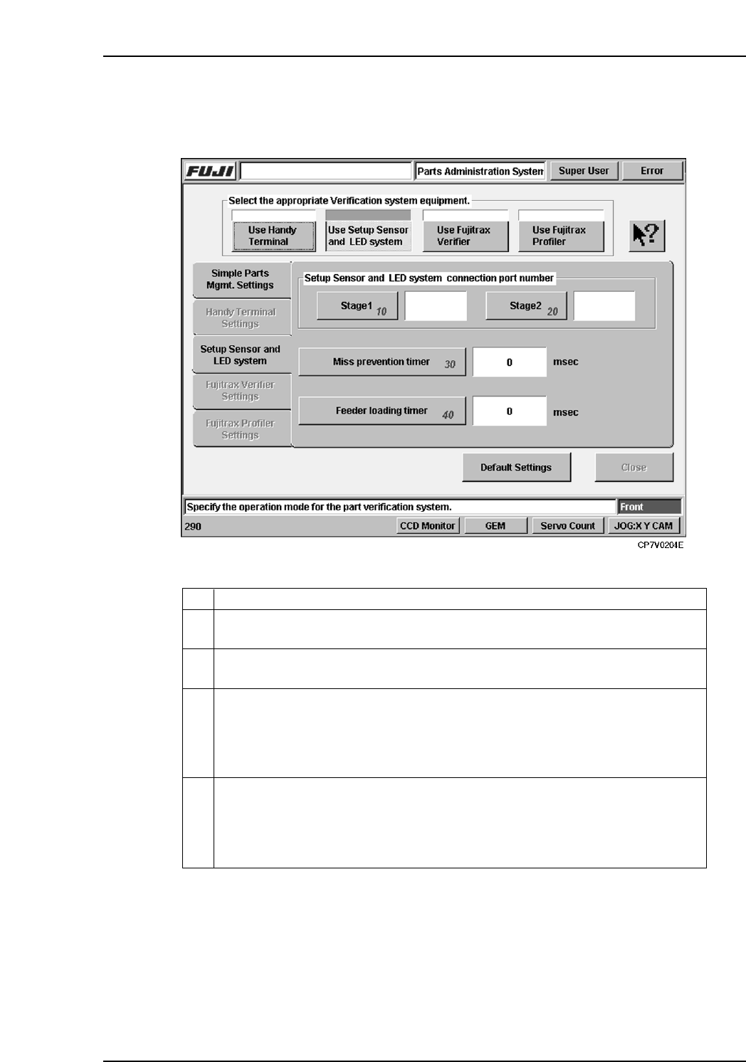
6.4 Setup Sensor & LED System Settings Tab
The setting items contained in the [Setup Sensor & LED System] tab are described below.
10 Specifies the communication port to which the Stage 1 setup sensor & LED
sequencer is to be connected.
Specifies the communication port to which the Stage 2 setup sensor & LED
sequencer is to be connected.
20
There may be cases in which several attempts are required in order to properly set
a feeder on the table. Because the feeder mount/demount sensor detects each of
these attempts, there could be cases when an incomplete verification status occurs
even though a normal verification has been executed. To prevent such problems,
feeder mounts and demounts which occur during this timer period are not recognized.
30
This is the timer used in normal verification operations which employ the Handy
Terminal. The machine monitors the time period from the point when a reel barcode
is read by the Handy Terminal, until the point when the feeder is set on the table.
If this timer period is exceeded, an incomplete verification status occurs because
the operator may have set a different feeder on the table.
40
ExplanationNo.
VT006E