N7201A304E05(1)_0.pdf - 第7页
NPM EJM9BE-BP-01N-12 Page 7 Wording in context How to read operating instructions Description depends on the page; ho wever, it is constructed basically as follows. 1.1.1 Starting Operation 1 Press in the main menu. 2 …
NPM
Page 6 EJM9BE-BP-01N-12
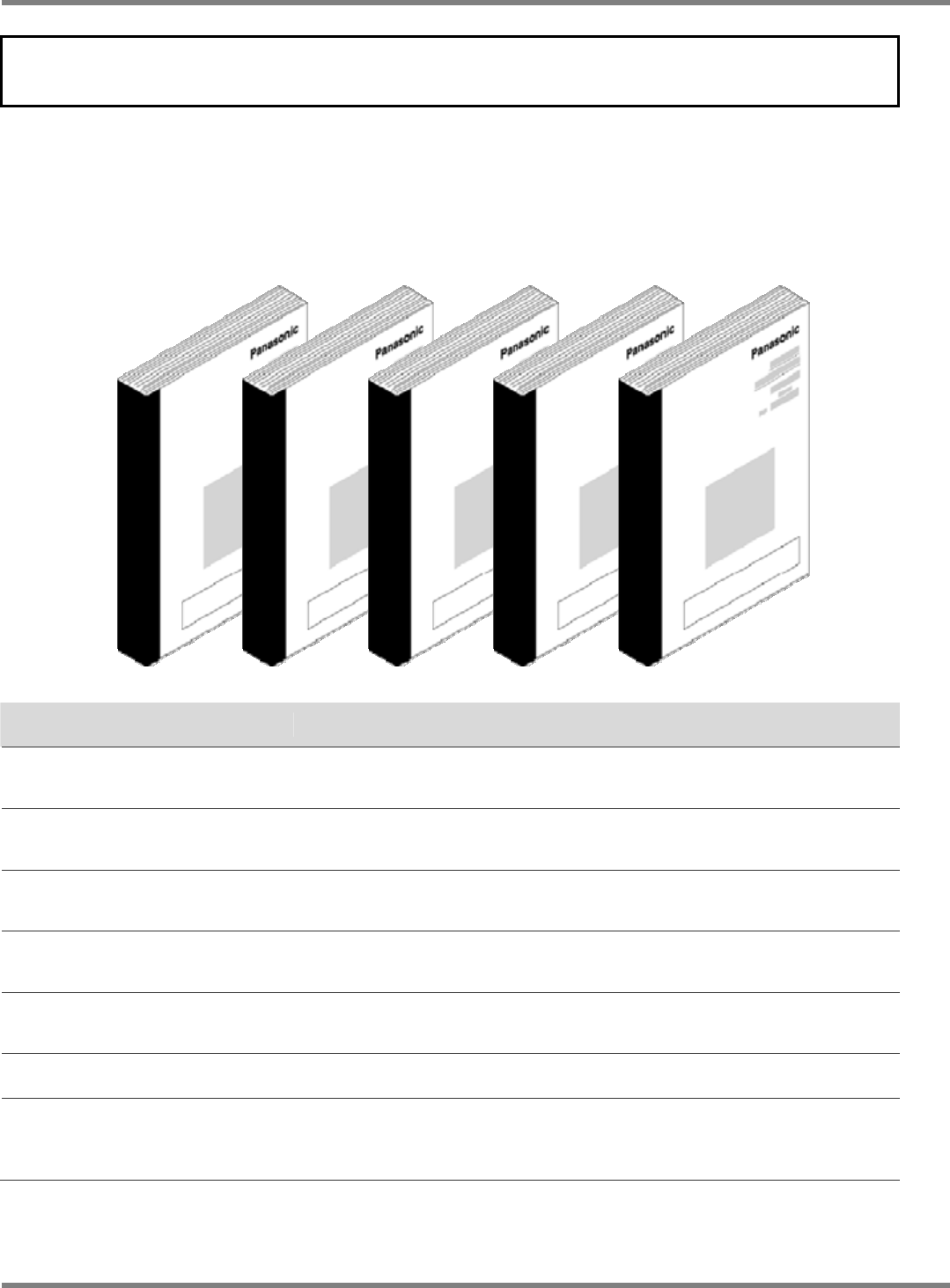
Organization of manuals
Organization of instruction manuals
This machine is accompanied with instruction manuals shown below.
Each of those manuals is designed for the purpose of a work. Refer to a manual suit for the
purpose of a work you will perform.
Machine data and on-line machine data are created with the data creation support system.
Please refer to the instruction manual accompanying the data creation support system.
Manual type Explanation
Installation Edition
This edition describes the machine installation procedures and the
overview of the machine.
Data Creation Edition
This edition describes data-related works such as production data
modification and data file management.
Production Edition
This edition describes production-related operation such as preparing parts
and specifying offsets.
Maintenance Edition
This edition describes the details of the inspection and adjustment that
should be performed periodically and replacement of consumable parts.
Troubleshooting
This edition describes errors that may be given by this machine and their
details.
LNB
This edition describes the LNB (Line Network Box).
Options
Options include the Multifunctional Transfer Unit, Parts Verification and
Host Communications, etc., each of which is described in the instruction
manuals provided with the respective units.
∗
When an option(s) is/are added to the NPM after delivery, explanation of that/those option(s)
may not be included in the machine manuals. Refer to manuals including the desired option(s)
or the manuals accompanying that/those option(s).
NPM
EJM9BE-BP-01N-12 Page 7
Wording in context
How to read operating instructions
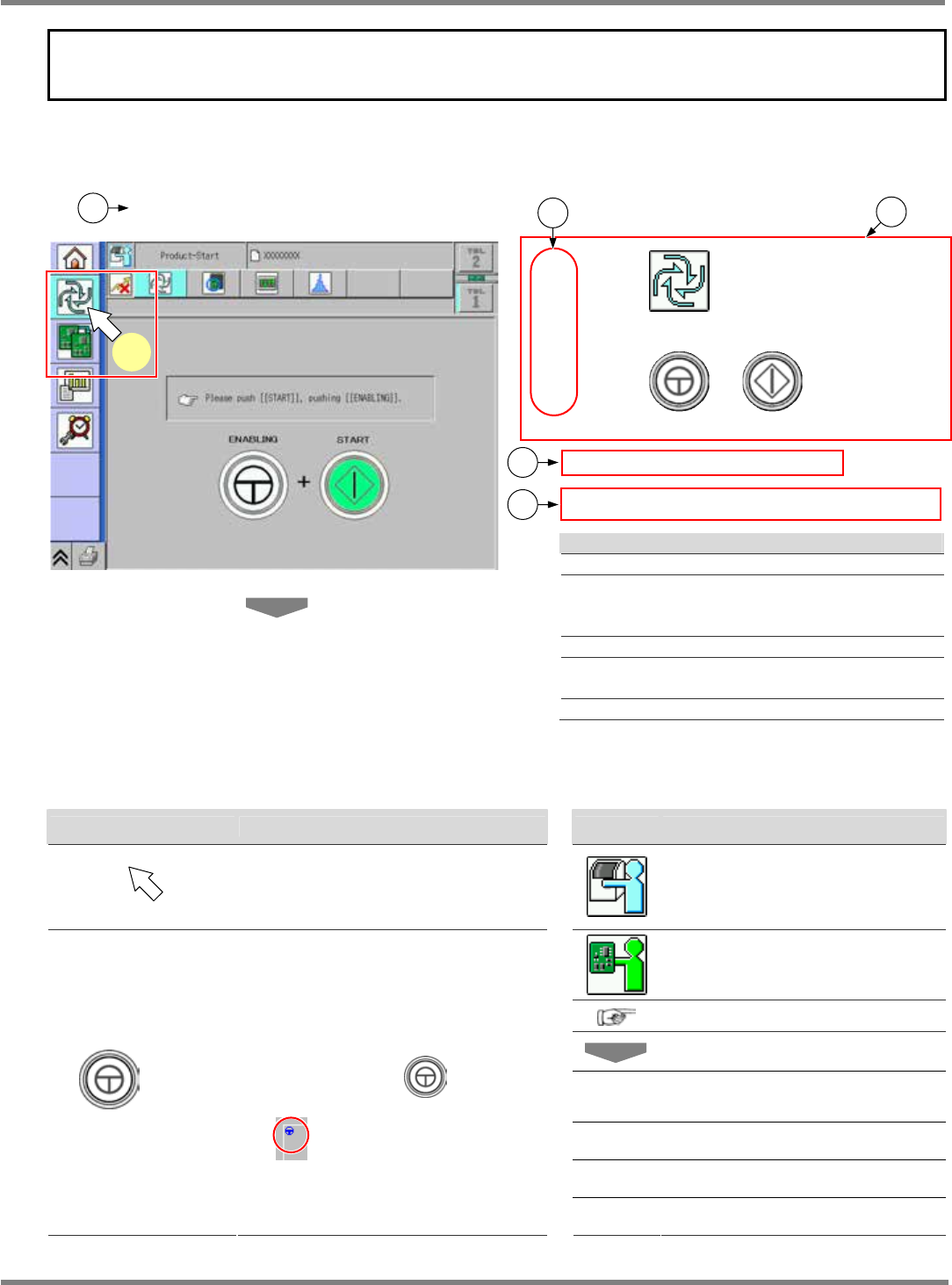
Description depends on the page; however, it is constructed basically as follows.
1.1.1 Starting Operation
1
Press in the main menu.
2
Press + .
•
The self-diagnosis process starts.
∗
If the servo switch is OFF (O), turn it ON ( I ).
Explanation
Title
Operation step number
Corresponds to the arrow number in a red
frame on the screen.
Actual operation
Describes the effect produced by the
operation.
Describes the supplementary explanation.
Symbols used in this manual
In this manual, the following symbols are used for description.
Symbol Explanation Symbol Explanation
Shows pressing a button on the color
touch panel.
Shows the operation for an
operator.
Shows the operation for an
engineer.
Shows a reference item.
Shows an operation flow.
<Screen
name>
Shows a screen name.
[Button] Shows a button or a menu.
“Message” Shows an on-screen message.
+ [ A ]
Indicates that you should press [A] on
the touch panel with
held down.
The button that requires this operation
has
mark in the upper left.
‘Item’ Shows an item on the screen etc.
ComEnabStart-02E00
1
1
3
2
4
5

NPM
Page 8 EJM9BE-CT-01N-21
TABLE OF CONTENTS
z
Safety Precautions...................................................................................................S-1
z
Labels pasted on product for safety...................................................................... S-17
z
Safety switches..................................................................................................... S-33
z
Lock out tagout procedure .................................................................................... S-33
z
Usage of warning sheets in maintenance............................................................. S-34
z
Stopping specifications when coupled.................................................................. S-35
z
The uninterrupted power connectors and the motor that does not stop if an
emergency stop switch is pressed........................................................................ S-36
z
Handling of linear motors...................................................................................... S-37
z
Handling of the line camera .................................................................................. S-38
z
Handling of the 3D sensor (option) ....................................................................... S-39
z
Handling of the vertical line camera (option) ........................................................ S-41
z
Handling of the change cart switch unit ................................................................ S-42
z
Handling of the wired scanner .............................................................................. S-44
z
Handling of the wireless scanner.......................................................................... S-45
z
Handling of SD card.............................................................................................. S-46
z
Serial number plate............................................................................................... S-48
z
Disposal of air spring ............................................................................................ S-50
z
Disposal or recycling of components containing mercury .................................... S-51
z
Repairs on or disposal of the linear motor ............................................................ S-52
z
Guidelines on using the machine.......................................................................... S-54