CP43操作手册.pdf.pdf - 第134页
SER VO ..............................Servo Boar d T race List Display .........................................SR V SER VO ..............................Servo Boar d T race List Display ..................................…

Part 3
Chapter 2 Table of Command Pages
3 – 8Version 5.0
PROPER...........................Setting Proper Data......................................................530/000
CAMERA.........................Measuring Camera Proper Data................................531/000
XC/YC .............................Mark Camera Reading Position/Power Setting......531/100
MARK ..............................Measuring the Mark Camera Position, Tilt..............531/200
WIDE ...............................
Wide View Parts Camera Resolution Measurement...531/300
NARROW .......................Narrow Parts Camera Resolution Measurement....531/400
BRIGHT............................Setting Camera Brightness..........................................531/500
MARK CAMERA ...........Setting Mark Camera Brightness...............................531/510
WIDE................................Setting Wide View Camera Brightness.....................531/520
NARROW........................Setting Narrow View Camera Brightness.................531/530
X/Y...................................Measuring Proper Data for X, Y Axis .......................532/000
...........................................Setting Proper Data for X, Y Axis..............................532/100
X0/Y0...............................Measures Proper Values X0/Y0.................................532/100
XL/YL..............................Measures Proper Values XL/YL................................532/100
XPCB/YPCB....................Measures Proper Values XPCB/YPCB......................532/100
Xmax/Ymax....................Measures Proper Values XMax/YMax .....................532/100
Xmin/Ymin.....................Measures Proper Values XMin/YMin ......................532/100
D1/D2/Z.........................Setting Proper Data for D1,D2 and Z Axis...............533/000
PICKUP POS...................Measuring D Axis Part Pickup Standard Position..533/100
PICKUP T1 ......................Setting D, Z Axis Proper Data....................................533/110
ORIGIN............................Setting D, Z Axis Origin Positions.............................533/200
D1 ORIGIN .....................Setting D1 Origin to Proper........................................533/200
D2 ORIGIN......................Setting D2 Origin to Proper........................................533/200
Z0......................................Setting the Z0 measurement results to Proper.........533/200
MAX LIMIT.....................Setting D, Z Axis Positive Stroke...............................533/300
MIN LIMIT......................Setting D, Z Axis Negative Stroke.............................533/400
SERVO..............................Making Servo-Related Settings..................................540/000
SPEED..............................Changing the Inching Speed......................................541/000
CONV. WIDTH...............Changing and Setting Conveyor Width...................542/000
MODE ..............................Changing the Servo Counter Display Mode............540/000
Command name Description
Command
page
FCP IV-3 Operation

SERVO..............................Servo Board Trace List Display.........................................SRV
SERVO..............................Servo Board Trace List Display......................................SRV-1
SERVO..............................Servo Board Trace List Printout...................................SRV-15
POSITION........................Moving to a Specified Position ..................................550/000
X AXIS..............................Moving the X Axis.......................................................551/000
Y AXIS..............................Moving the Y Axis.......................................................552/000
D AXIS..............................Moving to a Specified Device Position.....................553/000
D RESUPPLY...................Retracting the Device Tables ......................................554/000
DUMP PARTS.................Discarding Parts in Reject Part Box...........................555/000
POSITION........................Moving to a Specified Position ..................................550/000
X AXIS..............................Moving the X Axis.......................................................551/000
Y AXIS..............................Moving the Y Axis.......................................................552/000
COUNTER.......................Moving Y Axis to Target Position ..............551/000,552/000
PROGRAM......................Moving Y Axis to Placing Position Y.........551/000,552/000
D AXIS..............................Moving to a Specified Device Position.....................553/000
D RESUPPLY...................Retracting the Device Tables ......................................554/000
DUMP PARTS.................Discarding Parts in Reject Parts Box.........................555/000
Command name Description
Command
page
Chapter 2 Table of Command PagesPart 3
Version 5.0 3 – 9
FCP IV-3 Operation
FCP IV-3 Operation
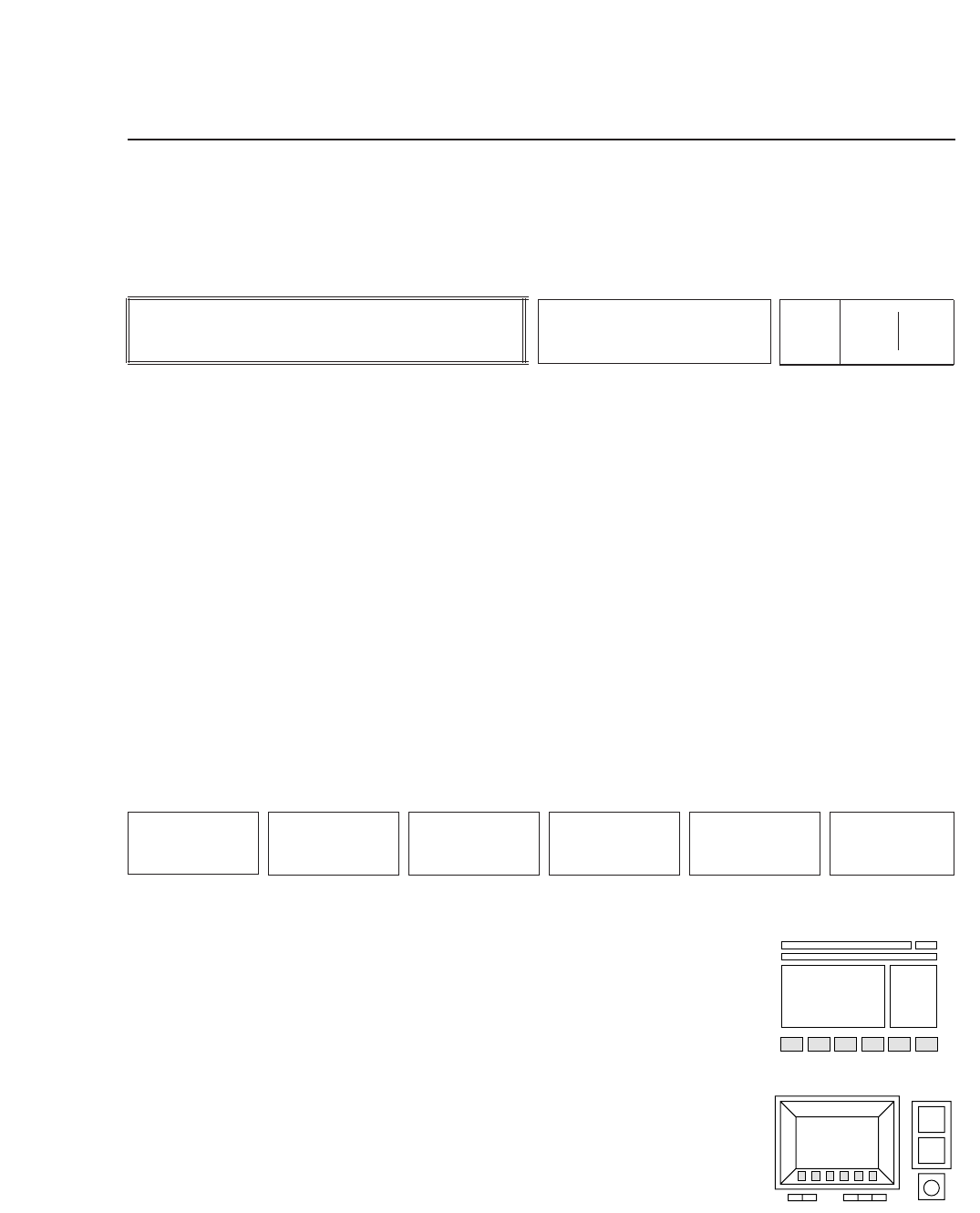
3. Description of Commands
This chapter explains each command using the format shown below.
The description of a command begins as shown above.
The left box describes the command, the center box names the command, and
the two boxes on the right comprise the command page number. The
command page number reflects the sequence of function keys that were pressed
to arrive at that page. For example, if the operator presses function key [F5],
command page number 500 displays. If [F2] is then pressed , command page
number 520 appears, and so on. In this fashion, the command page number
identifies a command's position within the command hierarchy. When more
than three function keys must be pressed to arrive at the desired command
page, only the numbers of the first three keys will actually display on the
machine. These are shown in the left portion of the box above. The numbers in
the right portion complete the sequence of function keys required to reach the
page.
The commands displayed in the function key menu are
shown here. The operator selects a command from the
function key menu by pressing the corresponding function
key, [F1] through [F6].
• Action of the Function Keys
Each command is listed here, along with an explanation of
what happens when the corresponding function key is
pressed.
• Function Key Menu
Chapter 3 Description of Commands
Part 3
3 – 10
F1
F2 F3 F4 F5 F6
Version 5.0
Description
COMMAND NAME
Page
000 000