CP43操作手册.pdf.pdf - 第59页
Part 1 1 – 46 FCP IV -3 Operation Chapter 6 Basic Operation V ersion 4.0

Part 1
6.8 Discarding Picked Parts
On the FCP IV-3 data is managed for the picked parts that are at each
station. In the case that distribution of part information to each station
cannot be guaranteed, the picked parts will unavoidably have to be
discarded in order to preserve placement accuracy and reliability.
The discarding of picked parts will be carried out in the following cases.
• After an emergency stop
After the occurrence of an emergency stop the status of the parts that
have been picked and vision processed may not have been preserved.
If the cam axis is rotated manually (using the cam handle) the picked
parts will be discarded since there is a possibility that the information
for the processed parts is different from the actual status of the parts.
• After the cam axis has been inched
For the same reason as mentioned above, picked parts will be
discarded if the cam axis is rotated via inching since there is a
possibility that the information for the processed parts will be
different from the actual status of the parts.
• After the placing sequence order has been changed
If the number of the placing sequence or a block skip is specified by a
command operation, the picked parts will be judged as useless and
thus discarded since the placing sequence order will have changed.
• Execution of the nozzle center measurement command
Picked parts will be discarded when nozzle center measurement is
carried out since these parts are a hindrance to the execution of this
command.
1 – 45
FCP IV-3 Operation
Chapter 6 Basic Operation
Version 4.0

Part 1
1 – 46
FCP IV-3 Operation
Chapter 6 Basic Operation
Version 4.0
Part 1
7. Nozzle Center Measurement
In order to achieve high placing accuracy, the FCP IV-3 stores data on the center
of rotation of nozzle holders, the amount of bend and other such data for each
nozzle. These values are used in effect for center compensation in the
measurement operation. Nozzle center measurement is an indispensable part
of being able to carry out highly accurate image processing.
This chapter provides an explanation of this nozzle center measurement.
7.1 An Explanation of Nozzle Center Measurement
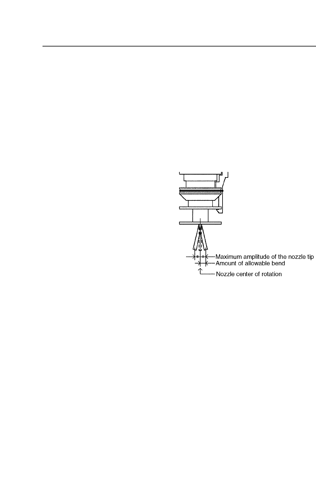
Nozzle center measurement
carries out a measurement of
the center of rotation of
nozzle holders. The amount
of bend in the nozzle is also
measured at the same time.
The distance from the center
of rotation to the nozzle tip is
calculated. The nozzle bend
is compared to the amount of
allowable bend (bend
tolerance) and a decision is
made. When the nozzle is
rotated 180° this yields the maximum amplitude of the nozzle tip and thus
the maximum amount of bend tolerance.
The nozzle center measurement is carried out twice on a single nozzle.
The first measurement looks at the current nozzle tip position. The
second measure of the nozzle tip position is carried out after the nozzle
has been rotated 180°. During this second measurement the maximum
amplitude of the nozzle tip, the center of rotation and the degree of nozzle
bend are calculated.
Further, in order to gain an image of the nozzle tip for nozzle center
measurement, image processing for a single nozzle is carried out using
both a standard (wide view) camera and a narrow view camera since the
camera resolution, field of vision and other such variables are different.
Note: The narrow field of view camera (in effect the image is magnified by this
camera) has a small area image and is not used to perform nozzle center
measurement on nozzles with a diameter 2.0 mm or greater.
1 – 47
FCP IV-3 Operation
Chapter 7 Nozzle Center Measurement
Version 5.0