CP43操作手册.pdf.pdf - 第31页
Part 1 Chapter 4 The Display (c) Production pr ogram name The name of the current pr oduction program is displayed here. The message “No prog” is displayed her e when no production program is loaded. The color of the pro…
Chapter 4 The DisplayPart 1
4. The Display
Almost all FCP IV-3 functions can be controlled from the operation panel,
which is comprised of the display monitor, operation keys and the push-button
switches.
4.1 CRT Display Monitor
The display monitor displays machine conditions and messages to the
operator.
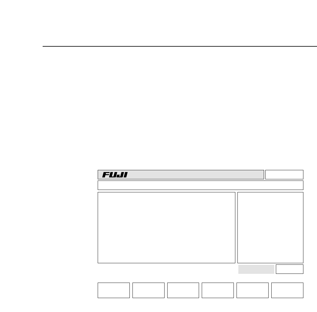
(a) Version number
The system ROM version number (e.g. V1.00, V1.10, V1.20, etc.) is
displayed here. This display allows verification of the version
number after ROM chip replacement.
(b) Line mode
This shows the MCS line communication mode currently in effect.
The word “Local” is displayed here if no production data is being
transmitted to the MCS 30 computer. When data is being transmitted,
the words “Off line” will appear.
Page 000
v1.10
Off line
CP_4.PROGRAM Prod 00000 Sche 00000
AUTO STEP LOADER PROGRAM SET
3A053C053C00
000000050000
jog X Y C
*
ST1.N**** D*** Er****
ST2.N**** D*** Er****
ST3.N**** D*** Er****
ST4.N**** D*** Er****
ST5.N**** D*** Er 0
ST6.N**** D*** Er 0
ST7.N**** D*** Er 0
STATUS
P Mode Product
Recovery 3 times
T Mode Joint
Machine Not Zero-Set
Press START
(a) (b)
(c)
(d) (e)
(f)
(g)
(h)
(i)
(j)
(k)
(l)
(m)
Ready
Board Loader
1 – 17Version 4.0
FCP IV-3 Operation

Part 1 Chapter 4 The Display
(c) Production program name
The name of the current production program is displayed here. The
message “No prog” is displayed here when no production program is
loaded. The color of the production program name changes
depending on the status of the vision processing board.
If the production program name displays in white it means that the
vision processing board is ready for use.
If the program name displays in yellow it means that the vision
processing board is being initialized.
If it displays in red it means that an error has occurred during
initialization of the vision processing board.
When the vision processing board is being initialized the machine will
not go into automatic operation. The message "Vision Processing
Board Booting..." will display.
Note: When the name of the production program displays in red, an error
code displays in the First Display Area shown as (g).
In this case, the power to the machine must be cut and then turned
back on again after fixing the error following "FUJI Error Code
Manual".
If the machine is rebooted without fixing the error, the production
program name displays in red again. If production is carried out
while the program name is displayed in red, a vision processing error
will occur.
(d) Completed production quantity
This shows the number of boards completed. This function occurs
only in Off Line mode. In Local mode boards will not be counted.
(e) Scheduled production quantity
This shows the scheduled quantity of boards to be produced. The
message “Sche 01000” would indicate that a total of one thousand
boards are to be produced. The message “Sche 00000” indicates that
no scheduled production quantity has been set, meaning that
production will continue indefinitely.
Note: Refer to Part 3, Chapter 3 of this manual, for further information
regarding the procedure used to set the scheduled production
quantity.
1 – 18
Version 5.0
FCP IV-3 Operation

Chapter 4 The DisplayPart 1
(f) First Status Area
This area displays the current command status. Command names
such as AUTO, LOADER, and SET appear here.
(g) First Display Area
This area displays information about the machine. Details regarding
the information displayed in this area are presented in Section 5.2.
(h) Second Display Area
This area displays error messages and comments to the operator.
Details regarding the information displayed in this area are presented
in Section 5.3 below.
(i) Second Status Area
This area displays additional comments that supplement the
information displayed in the First Status Area. Input from the
numerical keypad is also displayed here.
(j) Program counter
This counter is referred to when an abnormality occurs in operation of
the FCP IV-3. This counter is not referred to during normal operation.
(k) Inching axes
This display indicates which axes are currently selected for inching.
(l) Command page
The function key command page number is displayed here.
(m) Function key menu
The function keys (F1 through F6) are pressed to select commands.
Each function key corresponds to a command in the function key
menu portion of the FCP IV-3 display. To execute a command, press
the corresponding function key.
1 – 19
Version 5.0
FCP IV-3 Operation