CP43操作手册.pdf.pdf - 第199页
• Action of the Function Keys ▲ : Press to move the cursor up one line. Once the cursor has reached the top, if pr essed again it will move to the very bottom. ▼ : Press to move the cursor down one line. Once the cursor …
FCP IV-3 Operation
Note: The display characters have the following meaning.
* (yellow) : The first nozzle measurement has been completed.
0 (green) : The nozzle is normal.
0 (yellow) : There is a possibility that a vision processing error will
occur if this nozzle is used in production.
X (red) : The nozzle is abnormal (wrong size, etc.)
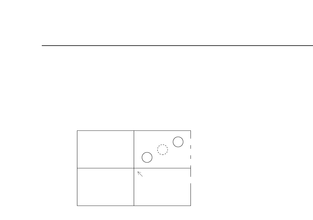
If the position of the nozzle center of rotation is as shown in the above figure, there
is the possibility depending on the size of the part, that the acquired image of the
part will not fit on the screen.
In such cases the message "HEAD ERROR" will display next to the nozzle in
question.
• Second Display Area
If start conditions are fulfilled, the message “Press START” flashes. Otherwise an
error displays.
Chapter 3 Description of Commands
Part 3
3 – 73
Version 5.0
Second nozzle measurement position
Center of rotation
First nozzle measurement position
Center of image acquisition

• Action of the Function Keys
▲ : Press to move the cursor up one line. Once the
cursor has reached the top, if pressed again it
will move to the very bottom.
▼ : Press to move the cursor down one line. Once
the cursor has reached the bottom, if pressed
again it will move to the very top.
RETURN : Press to return to page 523/100. The "Press
START" message for nozzle center
measurement begins flashing.
• Input from the Numerical Keypad
Enter bend tolerance values in units of 1/1000 mm using the
numerical keypad. For example, if you want to enter a value of
0.3mm, then enter 300 using the keypad and press the [CR] key.
If 0 is entered the tolerance will refer to the default value of 200
(0.2mm).
• First Display Area
NOZZLE BEND TOLERANCE SETTING
S NOZZLE TOL 00.000 [mm]
M NOZZLE TOL 00.000.[mm]
L NOZZLE TOL 00.000 [mm]
Normally, if a small tolerance is input for a nozzle which is
picking a small part, the check is quite severe.
• Function Key Menu
Chapter 3 Description of Commands
To Page 523/100
Measuring Nozzle Bend
Tolerance
Part 3
3 – 74
TOLERANCE
Page
523 110
▲ ▼
RETURN
Version 5.0
FCP IV-3 Operation
• Action of the Function Keys
Wide :Press to display the measured data on the wide
view parts camera.
Narrow :Press to display the measured data on the
narrow view parts camera.
RETURN :Press to return to page 523/100. The "Press
START" message for nozzle center
measurement begins flashing.
• Function Key Menu
Chapter 3 Description of Commands
To Page 523/151
To Page 523/152
To Page 523/100
Displaying Amount of Nozzle
Bend
Part 3
3 – 75
RESULTS
Page
523 150
WIDE NARROW RETURN
Version 5.0
FCP IV-3 Operation