CP43操作手册.pdf.pdf - 第197页
• Action of the Function Keys TOLERANCE : Press to set the nozzle bend tolerance. RESUL TS : Press to display the amount of nozzle bend. RETURN : Press to return to Page 520/000. • ST ART button Pressing the [ST AR T] bu…

• Action of the Function Keys
CENTER :Press to measure the feedback values for the
nozzle center and brightness.
SKIP :Press to allow nozzle skip to be set manually.
RETURN :Press to return to Page 520/000.
• Second Status Area
NOZZLE
• Function Key Menu
Chapter 3 Description of Commands
To Page 523/100
To Page 523/200
To Page 520/000
Nozzle Related Settings
Part 3
3 – 71
NOZZLE
Page
523 000
CENTER SKIP RETURN
Version 5.0
FCP IV-3 Operation
• Action of the Function Keys
TOLERANCE: Press to set the nozzle bend tolerance.
RESULTS : Press to display the amount of nozzle bend.
RETURN : Press to return to Page 520/000.
• START button
Pressing the [START] button begins the center measurement
where the center of rotation and brightness of each nozzle is
established. Defective nozzles are shown on the CRT.
• First Status Area
CENTER
• First Display Area
NOZZLE CONDITION
Wide View Camera Narrow View Camera
Head S L M Head S L M
A 0 0 0 G 0 0 0
B 0 0 0 H 0 0 0
C 0 0 0 I 0 0 0
D 0 0 0 J 0 0 0
E 0 0 0 K 0 0 0
F 0 0 0 L 0 0 0
STANDARD G S( 0, 0)
Wide View L M( 135, 237)
• Function Key Menu
Chapter 3 Description of Commands
To Page 523/110
To Page 523/150
To Page 520/000
Measuring Nozzle Centers
Part 3
3 – 72
CENTER
Page
523 100
TOLERANCE RESULTS
RETURN
Version 5.0
FCP IV-3 Operation
FCP IV-3 Operation
Note: The display characters have the following meaning.
* (yellow) : The first nozzle measurement has been completed.
0 (green) : The nozzle is normal.
0 (yellow) : There is a possibility that a vision processing error will
occur if this nozzle is used in production.
X (red) : The nozzle is abnormal (wrong size, etc.)
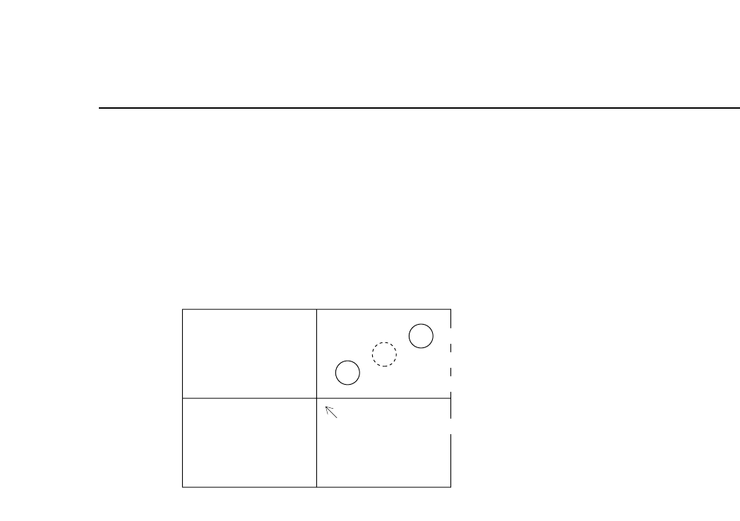
If the position of the nozzle center of rotation is as shown in the above figure, there
is the possibility depending on the size of the part, that the acquired image of the
part will not fit on the screen.
In such cases the message "HEAD ERROR" will display next to the nozzle in
question.
• Second Display Area
If start conditions are fulfilled, the message “Press START” flashes. Otherwise an
error displays.
Chapter 3 Description of Commands
Part 3
3 – 73
Version 5.0
Second nozzle measurement position
Center of rotation
First nozzle measurement position
Center of image acquisition