CP43操作手册.pdf.pdf - 第81页
Chapter 1 Automatic Operation Part 2 1.5 Device T able Mode On the FCP IV -3 there ar e three device table modes: joint mode, device change mode and changeover mode. An explanation of each mode follows. 1.5.1 Joint Mode …

Chapter 1 Automatic OperationPart 2
1.4 Cycle Stop
In automatic operation mode and while waiting to load the next board,
the machine can be stopped by pressing the [CYCLE STOP] button. When
this button is pressed the machine will stop at the end of the cycle and the
message "Press Start" will appear.
• Cam Axis Rotation
If the cam axis is at less than 280°, it will stop the next time it reaches
0°. If it has already reached 280˚ (nozzle change alarm) it will stop at
0˚ after making at least one full rotation.
• If the machine is reading fiducial marks or block skip marks it will
stop after these readings have been completed.
• If the machine is unloading the board, it will stop after the board is
unloaded.
• If the machine is loading the board, it will stop after the board has
been clamped.
• If the machine is waiting for the next board, the XY table will lower
and the machine will stop immediately.
• If the machine is performing zero setting, the machine will stop after
all axes have been zero set.
In all these cases, after the machine has stopped, the message “Press
START" will appear.
2 – 12Version 2.0
FCP IV-3 Operation

Chapter 1 Automatic OperationPart 2
1.5 Device Table Mode
On the FCP IV-3 there are three device table modes: joint mode, device
change mode and changeover mode. An explanation of each mode
follows.
1.5.1 Joint Mode
Tables 1 and 2 move jointly essentially as one large table capable of
handling up to 160 devices.
This mode is used in programs with a large number of parts.
Table 1 Table 2
View from the rear "Joint Mode"
The device table from which parts are being picked is referred to as
the "production table" while the table from which parts are not
being picked is called the "follow-up table".
1.5.2 Device Change Mode
Tables 1 and 2 are used separately. A maximum of 80 devices is
possible on each table. Either table 1 or 2 can be used, and the table
not in use is referred to as the spare table.
This mode can be used to eliminate down time on the production
line.
Table 1 Table 2
Original Table Spare Table
View from the rear "1A 2A"
The following flowchart shows how the tables are used when
operating in the device change mode.
Version 2.0
FCP IV-3 Operation
2 – 13
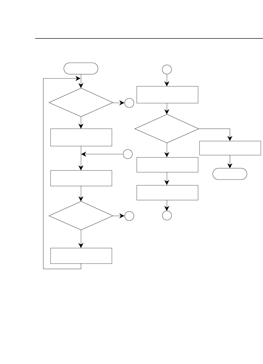
Chapter 1 Automatic OperationPart 2
Enter
Parts set on
original table?
Original table moves to
part picking position
Produce board
Have parts run out?
Board change
A
Original table moves to
resupply position
Parts set on
spare table?
Spare table becomes
original table
B
Exit
B
A
YES
NO
YES
NO
A
NO
Original table moves to
part picking position
Display parts
resupply message
2 – 14Version 2.0
FCP IV-3 Operation