CP43操作手册.pdf.pdf - 第65页
Part 1 (2) Making the setting on the MCS 30 computer V alues can be set in the production pr ogram with the MCS 30 Editor . Initially the values are set at 0.200 mm. Machine_data 45. S_bend_limit 0.000~2.000 [mm] = 0.200…

Part 1
7.4 Procedure
Measurement is automatically carried out by following the command key
operation below.
[SET] → [MANUAL] → [NOZZLE] → [CENTER]
Note: For information concerning the displays of this command key operation
refer to Part 3 Chapter 3, "Descriptions of Commands".
7.5 Setting the Maximum Nozzle Bend Tolerance
When placing the smallest
parts, the amount of nozzle
bend has a major influence
on picking accuracy and
the picking rate. On the
FCP IV-3 the nozzle bend
tolerance value can be set.
If the results of nozzle
center measurement yields
a value greater than the
bend tolerance value, this
allows that particular
nozzle to be clearly distinguished as "NG".
The nozzle bend amount is defined in the diagram to the right.
The 2 methods for setting the nozzle bend tolerance are explained below.
(1) Making the setting on the machine
To make the nozzle bend tolerance setting on the machine, press the
following command keys;
[SET] → [MANUAL] → [NOZZLE] → [CENTER] → [TOLERANCE]
Note: For information concerning the displays of this command key
operation refer to Part 3 Chapter 3, "Descriptions of Commands".
1 – 51
FCP IV-3 Operation
Chapter 7 Nozzle Center Measurement
Version 5.0

Part 1
(2) Making the setting on the MCS 30 computer
Values can be set in the production program with the MCS 30 Editor.
Initially the values are set at 0.200 mm.
Machine_data
45. S_bend_limit 0.000~2.000 [mm] = 0.200
This sets the bend tolerance for the nozzle affixed in the S holder.
46. M_bend_limit 0.000~2.000 [mm] = 0.200
This sets the bend tolerance for the nozzle in the M holder.
47. L_bend_limit 0.000~2.000 [mm] = 0.200
This sets the bend tolerance for the nozzle in the L holder.
1 – 52
FCP IV-3 Operation
Chapter 7 Nozzle Center Measurement
Version 5.0
Part 1
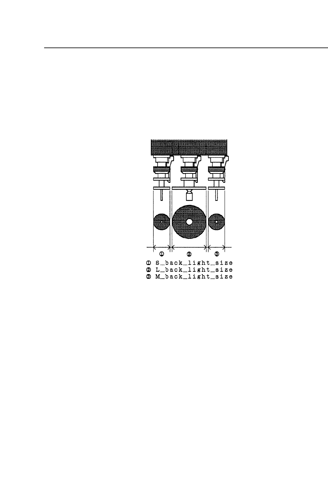
7.6 Setting the Nozzle Background Disk Diameter
On the FCP IV-3 the background disk diameter can be set which allows a
wider possible range of options related to what type of nozzle can be
affixed in each holder.
The background disk diameter for each nozzle is set in Machine_data in
the program.
Machine_data
42. S_back_light_size 0~50 [mm] = 12
This sets the background disk size (diameter) of the nozzle affixed in
the S holder. Initially this value is set at 12 mm.
43. M_back_light_size 0~50 [mm] = 12
This sets the background disk size (diameter) of the nozzle affixed in
the M holder. Initially this value is set at 12 mm.
44. L_back_light_size 0~50 [mm] = 25
This sets the background disk size (diameter) of the nozzle affixed in
the L holder. Initially this value is set at 25 mm.
1 – 53
FCP IV-3 Operation
Chapter 7 Nozzle Center Measurement
Version 5.0