CP43操作手册.pdf.pdf - 第200页
• Action of the Function Keys W ide : Press to display the measured data on the wide view parts camera. Narrow : Press to display the measur ed data on the narrow view parts camera. RETURN : Pr ess to return to page 523/…

• Action of the Function Keys
▲ : Press to move the cursor up one line. Once the
cursor has reached the top, if pressed again it
will move to the very bottom.
▼ : Press to move the cursor down one line. Once
the cursor has reached the bottom, if pressed
again it will move to the very top.
RETURN : Press to return to page 523/100. The "Press
START" message for nozzle center
measurement begins flashing.
• Input from the Numerical Keypad
Enter bend tolerance values in units of 1/1000 mm using the
numerical keypad. For example, if you want to enter a value of
0.3mm, then enter 300 using the keypad and press the [CR] key.
If 0 is entered the tolerance will refer to the default value of 200
(0.2mm).
• First Display Area
NOZZLE BEND TOLERANCE SETTING
S NOZZLE TOL 00.000 [mm]
M NOZZLE TOL 00.000.[mm]
L NOZZLE TOL 00.000 [mm]
Normally, if a small tolerance is input for a nozzle which is
picking a small part, the check is quite severe.
• Function Key Menu
Chapter 3 Description of Commands
To Page 523/100
Measuring Nozzle Bend
Tolerance
Part 3
3 – 74
TOLERANCE
Page
523 110
▲ ▼
RETURN
Version 5.0
FCP IV-3 Operation
• Action of the Function Keys
Wide :Press to display the measured data on the wide
view parts camera.
Narrow :Press to display the measured data on the
narrow view parts camera.
RETURN :Press to return to page 523/100. The "Press
START" message for nozzle center
measurement begins flashing.
• Function Key Menu
Chapter 3 Description of Commands
To Page 523/151
To Page 523/152
To Page 523/100
Displaying Amount of Nozzle
Bend
Part 3
3 – 75
RESULTS
Page
523 150
WIDE NARROW RETURN
Version 5.0
FCP IV-3 Operation
• Action of the Function Keys
RETURN :Press to return to page 534/500. The "Press
START" message for nozzle center
measurement begins flashing.
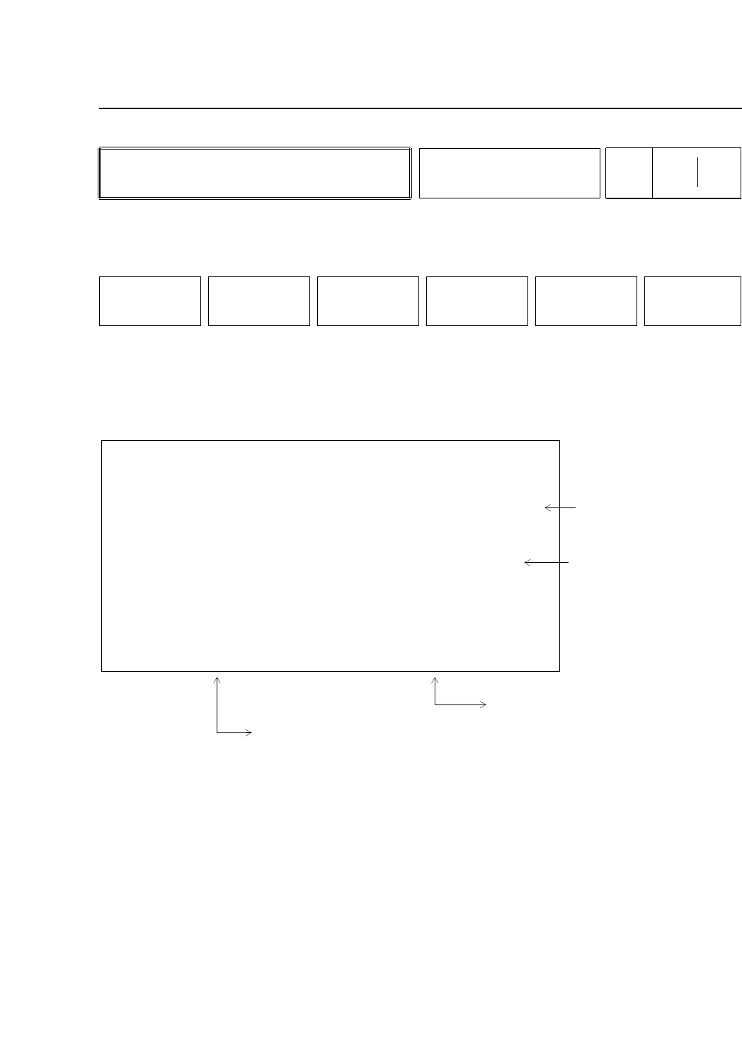
(a) The amount of allowable nozzle bend displays.
(b) Head errors display here. If there is a large discrepancy
between the nozzle center or rotation and the center of
the acquired image, the image of the part may be larger
than the nozzle depending on the size of the picked
part. The heads of these nozzles display here.
(c) NG displays if the actual nozzle diameter is not within
±15% of the nozzle diameter set in the program.
(d) The distance between the measured center of rotation
and the nozzle tip displays here. The display is in green
if the measurement is within the set tolerance and in red
if the measurement is outside of the set tolerance.
• Function Key Menu
Chapter 3 Description of Commands
To Page 523/000
Displaying Amount of Nozzle
Bend
Part 3
3 – 76
WIDE / NARROW
Page
523 151
152
RETURN
Version 5.0
FCP IV-3 Operation
HEAD A
HEAD B
HEAD C
HEAD D
HEAD E
HEAD F
HEAD G
HEAD H
HEAD I
HEAD J
HEAD K
HEAD L
0.000
0.000
0.000
0.000
0.000
0.000
0.000
0.000
0.000
0.000
0.000
0.000
OK
OK
OK
OK
OK
OK
OK
OK
OK
OK
OK
OK
NG
NG
NG
NG
NG
NG
NG
NG
NG
NG
NG
NG
0.000
0.000
0.000
0.000
0.000
0.000
0.000
0.000
0.000
0.000
0.000
0.000
OK
OK
OK
OK
OK
OK
OK
OK
OK
OK
OK
OK
S 0.000
M 0.000
L 0.000
LIMIT
B ENT NOZZLE [mm] AND NOZZLE DIAMETER CHECK
Problem head
A-S B-M
B-L
Results of nozzle diameter check
OK: Nozzle diameter is same as specified
NG: Nozzle diameter is different than
the specified diameter
Nozzle bend limit settings
Head errors display here.
Errors are determined by
comparing the holder center
of rotation with the image
acquisition area.
A-S stands for the S nozzle
on the A head.
Nozzle bend measurement results
(a)
(b)
(c)
(d)