SIPLACE-SX4-DX4-用户手册.pdf - 第100页
Service Work Conveyor 3.6.3 Replacing the Clamps 100 Service Manual SIPLACE SX4/DX4 3.6.3 3 . 6 . 3 R e p la c in g t h e C la m p s Replacing the Clamps Parts, equipment and tools ▪ Clamping unit SX4 1.1 [03084719-xx] ▪…
Service Work
3.6.2 Manual Removal of Large Boards Conveyor
Service Manual SIPLACE SX4/DX4 99
3.6.2
3.6.2 Manual Removal of Large Boards
Manual Removal of Large Boards
In some cases (e.g. for mapping) you may need to remove large boards manually from the conveyor.
Parts, Equipment and Tools
▪ Metal ruler or angle bracket
Procedure
► Move the conveyor rail back to the innermost position and retighten the fastening screws. Also ob-
serve the following instructions:
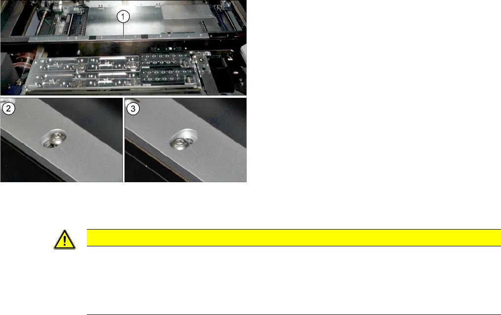
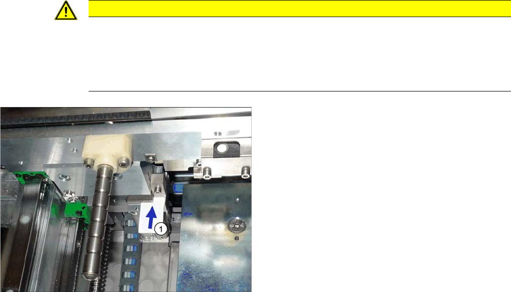
► Loosen the screws fastening the conveyor rail (1).
However, do not fully remove the screws.
► Move the conveyor rail within its slot from the inner-
most (2) to the outermost (3) position.
► Remove the board.
CAUTION
Installation instructions
► Make sure that the conveyor rail is flush with the clamping plate. There should be no pro-
jecting edge. Components on the boards could collide with clamping rails which are not
flush or could be irrevocably damaged during clamping. Check the fit with a metal ruler or
angle bracket.
Service Work
Conveyor 3.6.3 Replacing the Clamps
100 Service Manual SIPLACE SX4/DX4
3.6.3
3.6.3 Replacing the Clamps
Replacing the Clamps
Parts, equipment and tools
▪ Clamping unit SX4 1.1 [03084719-xx]
▪ Clamping unit SX4 2.1 [03084754-xx]
Removal
► Use the software to move the conveyor sides into the position which allows you best access.
► You may need to loosen the conveyor trolley sides, if this gives you better access. (see "3.6.1 Loos-
ening the Conveyor Side Clamps" [ ➙ 95]).
► Switch off the machine, disconnect it from the power supply and secure it to prevent unauthorized
reactivation. Observe the instructions in section "1.2 Preparatory Work..." [ ➙ 12].
► Loosen the clamp on the clamping unit with a pin or a 3mm screw. (See above)
► Dismantle the clamping unit.
Installation
Installation is performed by following the above instructions in the reverse order. Also observe the fol-
lowing instructions:
CAUTION
Installation instructions
► During installation, you need to set a gap of 0.3 mm between the clamping unit (fixed with
a pin or a 3 mm screw) and the clamping surface. Check this gap with a feeler gauge (see
following diagram).
► Remove all pins from the conveyor edge clamps.
1. The gap between the clamping unit and the clamping
surface must be 0.3 mm.
Service Work
3.6.4 Replacing the Lifting Table Unit Conveyor
Service Manual SIPLACE SX4/DX4 101
3.6.4
3.6.4 Replacing the Lifting Table Unit
Replacing the Lifting Table Unit
Parts, equipment and tools
▪ DC/QL lifting table type A [03075652-xx] or
SC lifting table type A - DX4 [03082396-xx]
▪ Depth measuring gauge (200 mm) [03079617-xx]
Overview
Removal
► Use the software to move the conveyor sides to a position which gives you good access to the lifting
table fixtures.
► Switch off the machine and secure it to prevent unauthorized reactivation. Observe the instructions
in section "1.2 Preparatory Work..." [ ➙ 12].
► Loosen the conveyor side clamps. (see "3.6.1 Loosening the Conveyor Side Clamps" [ ➙ 95]).
► Loosen the four screws fastening the two lifting table plates and remove the lifting table plates from
the machine. Make sure that the plates are not swapped over by mistake.
► Mark the positions of the lifting table plate fixtures to make it easier to refit them later on. These fix-
tures are used to set the height and parallelism of the lifting table plates. If these are not reinserted
in exactly the same positions, you will need to totally realign the lifting table plates after installation.
CAUTION
Lifting table motor
The lifting table motor can not be replaced on DC/QL conveyors. In this case you need to re-
place the entire lifting table. Do not take the lifting table mechanism apart.
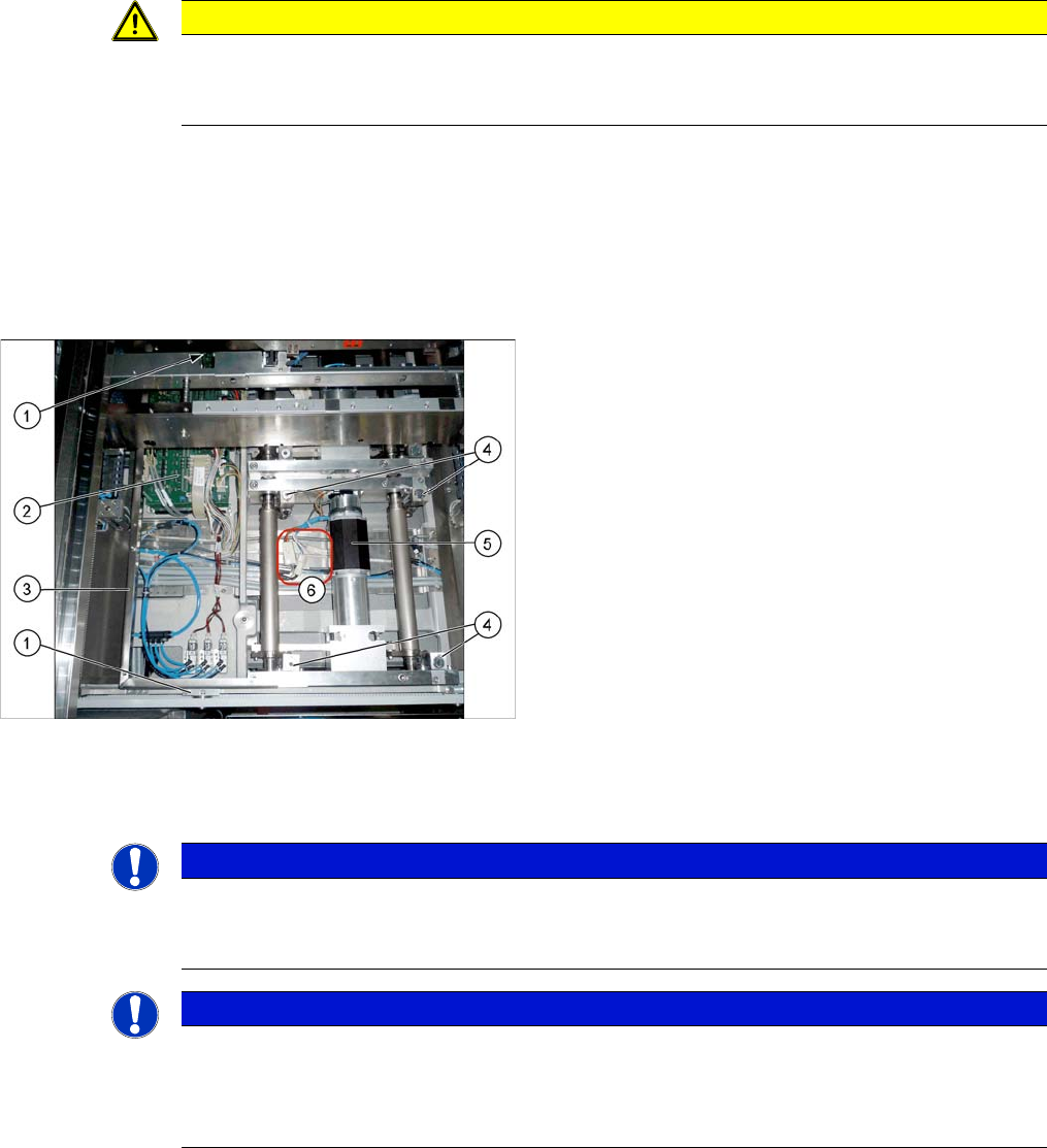
Lifting table dual conveyor
1. Four screws fastening the conveyor control mounting
frame
2. Conveyor control
3. Conveyor control frame
4. Four lifting table plate fixtures
These are part of the lifting mechanism.
5. Lifting table motor
6. Electrical connections for the lifting table motor
NOTICE
Dual and single conveyor
The removal is shown in the diagram using the example of a lifting table unit for the dual con-
veyor (DC). Replacement of the lifting table unit for the single conveyor (SC) is the same.
NOTICE
Lifting table up?
If the lifting table stays in the top position, you first need to disconnect the motor from the rods.
(See "3.6.4.1 Manually Lowering the Lifting Table" [ ➙ 103])
If this is not possible, contact your SIPLACE Service team.