SIPLACE-SX4-DX4-用户手册.pdf - 第203页
Service Work 3.13.3 Removing the Front Section of the Manual T able Ma nual Tab le (DX4) Service Manual SIPLACE SX4/DX4 203 Removal ► Dismantle the back section of the manual table. (See "3.13.2 Re moving the Back S…
Service Work
Manual Table (DX4) 3.13.3 Removing the Front Section of the Manual Table
202 Service Manual SIPLACE SX4/DX4
3.13.3
3.13.3 Removing the Front Section of the Manual Table
Removing the Front Section of the Manual Table
Parts, equipment and tools
▪ Rubber mallet
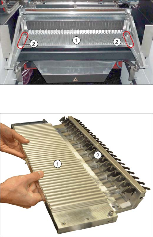
Overview
Manual table – front section (using the example of the
DX1/DX2)
1. Front part
2. Screws fastening the front section (4x)
1. Front part
2. Feeder locking device
This is fixed from below with 6 screws.
Service Work
3.13.3 Removing the Front Section of the Manual Table Manual Table (DX4)
Service Manual SIPLACE SX4/DX4 203
Removal
► Dismantle the back section of the manual table. (See "3.13.2 Removing the Back Section of the Man-
ual Table" [ ➙ 201])
► Loosen the fastening screws of the feeder locking device and then remove the board.
► Loosen the 4 screws fastening the front section.
► Pull the module out of the locating pins. You may need to use a rubber mallet to help you.
Installation
► Follow the removal instructions in reverse order for installation.
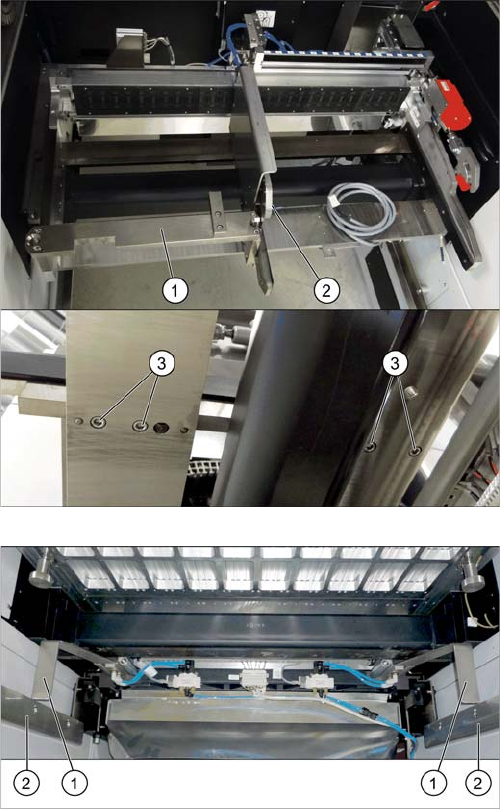
If there is a WPC at the same location, perform the follow-
ing two steps as well:
► Dismantle the WPC docking rail (1).
► Dismantle the left side of the insert mechanism (2).
Loosen the 4 fastening screws (3) on the underside
and the 2 fastening screws on the top of the empty
tape duct.
► Dismantle the stoppers (1).
You may need to lower the cutter onto the support
plates (2). (See Replacing the Cutter [03063781Sxx])
Service Work
Manual Table (DX4) 3.13.4 Replacing the Locking Latch [03069205-xx]
204 Service Manual SIPLACE SX4/DX4
3.13.4
3.13.4 Replacing the Locking Latch [03069205-xx]
Replacing the Locking Latch [03069205-xx]
Parts, equipment and tools
▪ Single locking latch [03069205-xx]
▪ Tension spring [03010352-xx]
▪ Cover plate for locking strip [03077142-xx]
Removal/installation
► Dismantle the front and back sections.
► The procedure is the same for the component trolley. Please refer the instructions in section "3.11.2
Replacing the Locking Latch [03069205-xx]" [ ➙ 184].
See also
3.13.6.1 Operating the Unlocking Hook [ ➙ 208]
3.13.5 Replacing the Feeder Lock on the Manual Table [03082778-xx] [ ➙ 204]
3.13.5
3.13.5 Replacing the Feeder Lock on the Manual Table [03082778-xx]
Replacing the Feeder Lock on the Manual Table [03082778-xx]
Please also observe section "3.11.2 Replacing the Locking Latch [03069205-xx]" [ ➙ 184].
Parts, equipment and tools
Select the correct spare part:
▪ Rubber mallet
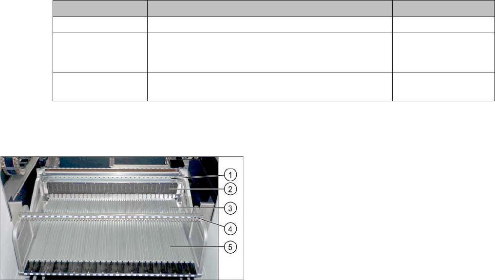
Overview
Machine type Designation Item No.
X-Series S Feeder lock/X-Series (1x) 03023777-xx
SX1/SX2, DX1/DX2 Feeder lock 30/2-fold
(1x per 30 track manual table or component trolley)
(2x per 60 track manual table or component trolley)
03081586-xx
DX4 Feeder lock 40-fold
(1x per manual table or component trolley)
03082778-xx
Manual table (using example of DX1/DX2)
1. Centering bar
2. FCU
3. Front section with feeder lock (with locking latches)
4. Fixture bar
5. Back part