SIPLACE-SX4-DX4-用户手册.pdf - 第40页
Service Work Electrical System 3.2.5 Replacing the AC/DC Converter (Pulsed Po wer Packs A5 to A8) 40 Service Manual SIPLACE SX4/DX4 3.2.5 3 . 2 . 5 R e p la c in g t h e A C / D C C o n v e r t e r ( P u ls e d P o w e r…
Service Work
3.2.4 Checking the Input Voltage on the Transformer Module Electrical System
Service Manual SIPLACE SX4/DX4 39
3.2.4
3.2.4 Checking the Input Voltage on the Transformer Module
Checking the Input Voltage on the Transformer Module
Procedure
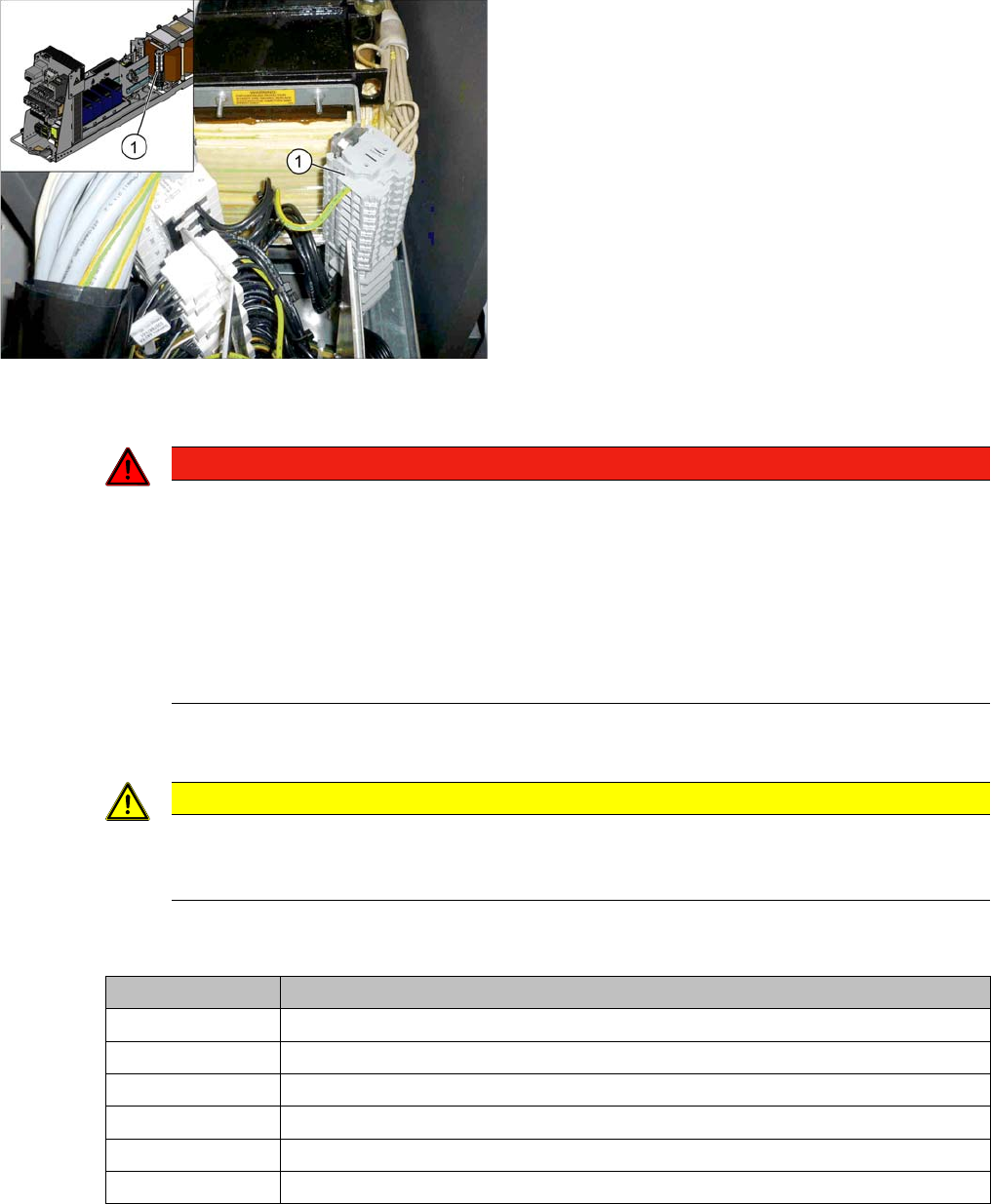
► Check the terminal panel, to make sure that the primary end of the three-phase transformer is con-
nected correctly for the required supply voltage.
The following overview shows the connection options for the primary voltages of the three-phase trans-
former:
1. Terminal panels with primary connections for the
three-phase transformer
The primary end of the three-phase transformer needs to
be configured for the respective supply voltage.
DANGER
Observe the safety instructions
There is a risk of dangerous touch voltages and short circuits occurring in transformer modules
which have been made accessible and are connected for measurement purposes.
Nonobservance of these safety instructions may cause injury to personnel and damage to the
machine!
Measurements may only be performed by specially trained service technicians, with appropri-
ate qualifications and expertise.
► Observe the instructions in section "1.1.3 Safety Instructions for the Power Supply" [ ➙ 10].
CAUTION
Power supply networks in Japan and USA
The Japanese power supply network (3x 200 V~) and the power supply networks in the USA
(3x 208 V~) are connected to the terminals for 3x 204 V~.
Terminal panel Voltage
1U1, 1V1, 1W1 415 VAC
1U3, 1V3, 1W3 400 VAC
1U4, 1V4, 1W4 380 VAC
1U5, 1V5, 1W5 230 VAC
1U6, 1V6, 1W6 220 VAC
1U7, 1V7, 1W7 204 VAC
Service Work
Electrical System 3.2.5 Replacing the AC/DC Converter (Pulsed Power Packs A5 to A8)
40 Service Manual SIPLACE SX4/DX4
3.2.5
3.2.5 Replacing the AC/DC Converter (Pulsed Power Packs A5 to A8)
Replacing the AC/DC Converter (Pulsed Power Packs A5 to A8)
Parts, equipment and tools
▪ AC/DC converter (pulsed power pack – A5, A6, A7) [03055232-xx]
▪ AC/DC converter (pulsed power pack – A8) [03076588-xx]
Overview
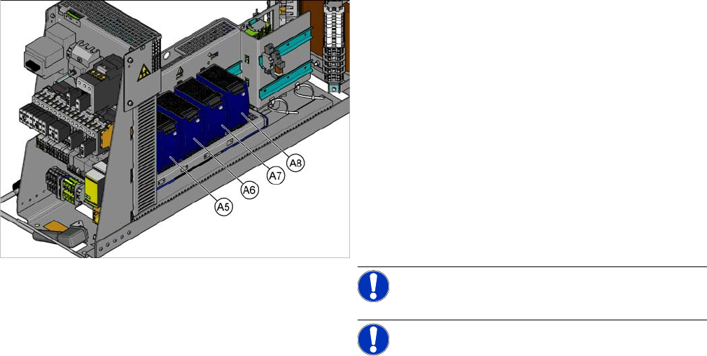
SX4 X34iS – Ov erview of Pul sed Power Pac ks
The pulsed power packs are located in the rack unit be-
tween location 3 and 4.
A5) Pulsed power pack (24 VDC, set to 25 VDC)
for Power Fail, safety circuit SSK, tape cutter, PCB Han-
dling
The power fail signal is generated by the pulsed power
pack A5 and sent to the GCU and HCU. (X200:9,
X200:10)
A6) Pulsed power pack (27 VDC)
for FCU (gantry 1 and 4)
A7) Pulsed power pack (27 VDC)
for FCU (gantry 2 and 3)
A8) Pulsed power pack (36 VDC, to be set to 42 VDC)
For HCU (gantry 1 to 4)
NOTICE!
NOTICE! Check the set values and correct if
necessary.
To A5:
The following fuses have 24 V present:
F10: Conveyor electrics
F11: Y motor fan, safety circuit (internal)
F12: Distributor power (line 1)
F13: Distributor power (line 2)
F14: Power fail
F20: Cover fan, gantry 1 and 4
F21: Cover fan, gantry 2 and 3
Service Work
3.2.5 Replacing the AC/DC Converter (Pulsed Power Packs A5 to A8) Electrical System
Service Manual SIPLACE SX4/DX4 41
Removal
► Switch off the machine, disconnect it from the power supply and secure it to prevent unauthorized
reactivation. Observe the instructions in section "1.2 Preparatory Work..." [ ➙ 12].
► Unplug all connections to the module. You may want to mark their positions, to make clear assign-
ment easier later on.
Installation
► Follow the removal instructions in reverse order for installation. Also observe the following instruc-
tions:
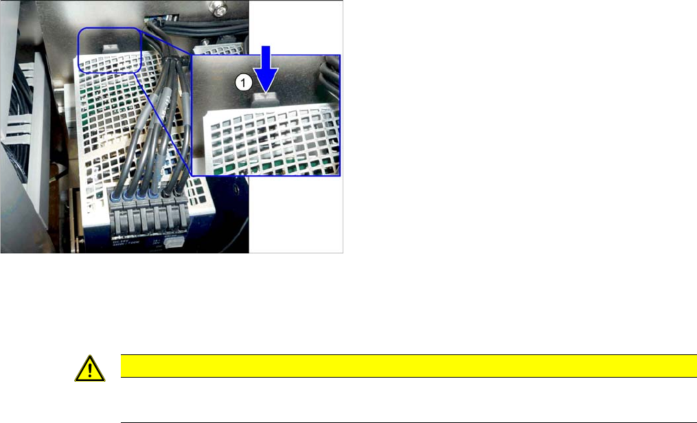
► To release the module, press the lever (1) at the back
of the module down and then pull the module off the
rail.
CAUTION
Installation instructions
► Set the voltage. (See "5.2.2 Setting the Voltage on the Pulsed Power Packs" [ ➙ 234])