SIPLACE-SX4-DX4-用户手册.pdf - 第230页
Settings Settings on the Basic Machine 5.1.1 Setting the Machine Covers 230 Service Manual SIPLACE SX4/DX4 5.1.1.3 5 . 1 . 1 . 3 S e t t in g t h e C o v e r S w it c h C e n t e r in g D e v ic e Setting the Cover Switc…
Settings
5.1.1 Setting the Machine Covers Settings on the Basic Machine
Service Manual SIPLACE SX4/DX4 229
5.1.1.2
5.1.1.2 Setting the Cover Switch
Setting the Cover Switch
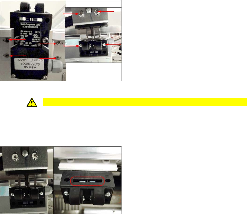
Cover switch (using example of SX2)
Cover switch [03055262-xx]
► Loosen the screws fastening the cover switch, the
centering device and the actuator, so that the assem-
blies can be easily moved.
CAUTION
Screws on actuator
With enforcement of the Machinery Directive DIN EN 1088 (2009), the following has been ex-
ecuted to avoid misuse (e.g. putting the safety features out of action): the actuator and machine
protective switch screws have been replaced by Torx screws with pins. The relevant set of tools
may only be used for performing repair work.
Cover switch (using example of SX2)
► Close the cover far enough for the actuator to be just
over the switch. Align them so that the metal bracket
is parallel to the opening in the switch. The metal
bracket may not scrape against the cover switch.
► Tighten the cover switch screws in this position.
Settings
Settings on the Basic Machine 5.1.1 Setting the Machine Covers
230 Service Manual SIPLACE SX4/DX4
5.1.1.3
5.1.1.3 Setting the Cover Switch Centering Device
Setting the Cover Switch Centering Device
5.1.1.4
5.1.1.4 Setting the Actuator
Setting the Actuator
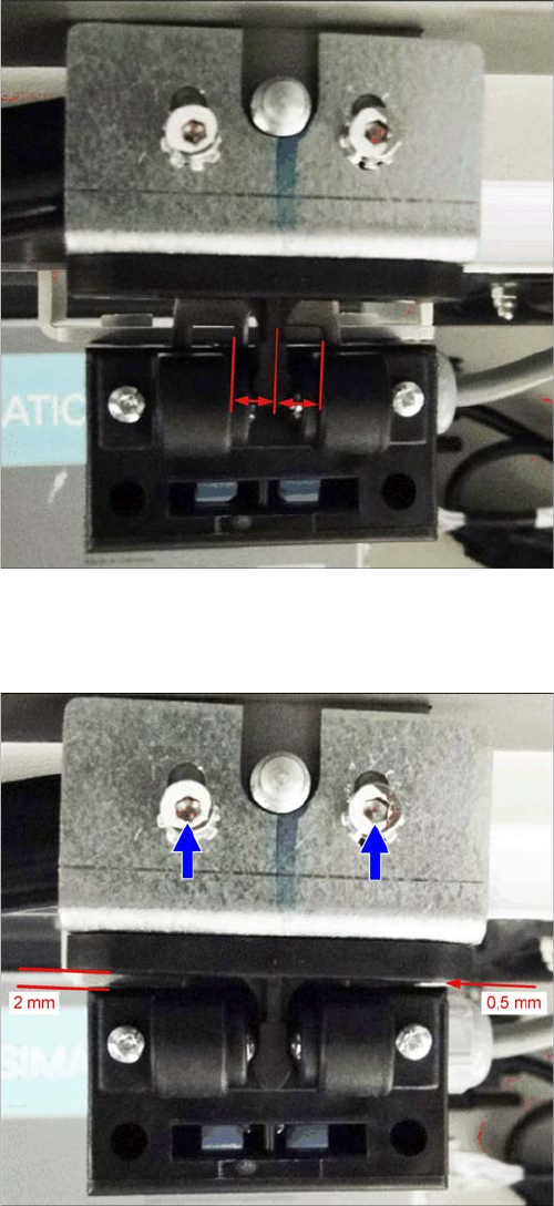
Cover switch (using example of SX2)
► Close the cover a little more until the plastic centering
device for the actuator is against the cover switch
centering device. These two must be centered to-
wards one another.
► Tighten the screws for the cover switch centering de-
vice.
Setting (example of SX2 shown)
Actuating bracket B1-2053 for AZ15/16 [00321649-xx]
► Close the cover completely.
► Set the actuator so that it stands approx. 2 mm above
the machine center and tighten the screws.
Settings
5.1.1 Setting the Machine Covers Settings on the Basic Machine
Service Manual SIPLACE SX4/DX4 231
5.1.1.5
5.1.1.5 Setting the Bottom Stop
Setting the Bottom Stop
► Check the settings by opening and carefully closing the cover several times:
▪ The metal bracket is parallel to the opening and does not scrape against the switch
▪ The plastic centering feature is positioned centrally to the centering device and does not scrape
against the switch.
▪ When the cover is opened, there is no discernable resistance of the cover rollers in the guidance
rails.
▪ Shortly before the bottom cover position, there is no resistance audible apart from the centering en-
gaging and the engaging of the metal bracket in the cover switch.
▪ The cover can be closed completely, so that the swing cover closes smoothly at the top with the side
covers.
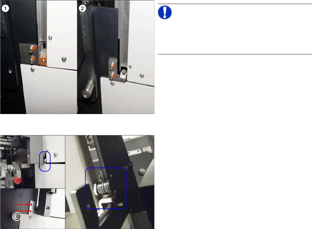
Bottom stop (example of SX2 shown )
NOTICE!
There are two variations of the bottom stop. These are
not exchangeable with one another. When replacing
these two variants, you also need to replace the gantry
changer doors and the guidances.
1. Variant 1:
2x buffer cover guidance [03075364-xx]
1x DIN EN ISO7380-M3 x 25-A2-70 [03045198-xx]
1x DIN985 - M3 - A2-70 [00328897-xx]
2. Variant 2:
Right stop [03086295-02]
Left stop [03086313-02]
Buffer with studs, type no. 1284 [03072728-01]
Guide roller (example of SX2 shown)
► Adjust the bottom stop for the guide rollers so that the
actuator does not touch the housing of the switch and
so that the upper cover is parallel to the side machine
cover. The foam rubber on the bottom stop must lie
against the roller, without the cover being pressed
back up again. This must be set for both sides.