SIPLACE-SX4-DX4-用户手册.pdf - 第97页
Service Work 3.6.1 Loosening the Conveyor Side Clamps Conveyor Service Manual SIPLACE SX4/DX4 97 3.6.1.2 3 . 6 . 1 . 2 M o v in g t h e C o n v e y o r S id e s b y M a n u a lly R e le a s in g t h e S id e C la m p s M…
Service Work
Conveyor 3.6.1 Loosening the Conveyor Side Clamps
96 Service Manual SIPLACE SX4/DX4
3.6.1.1
3.6.1.1 Manually Moving the Conveyor Sides with the Help of the Adjustment Units
Manually Moving the Conveyor Sides with the Help of the Adjustment Units
Docking in the adjustment units
If you are unable to move the sides with the software (e.g. due to a sensor error), proceed as follows:
► Switch off the machine.
► Switch off the BoxPC.
► Create access for the solenoid valves to the adjustment units:
SX1/SX2: Dismantle the lifting table plate at location 2.
SX4/DX4: Dismantle the cover next to the lifting table plate at location 4.
X-Series S: Dismantle the lifting table plate at location 3.
► Switch the machine on (without BoxPC). The machine is now supplied with compressed air.
Solenoid valves (example of SX1/SX2 shown)
► Carefully pull on the width adjustment belt to move
the adjustment units until they are under the clamps
and the short-stroke cylinder can activate the clamps.
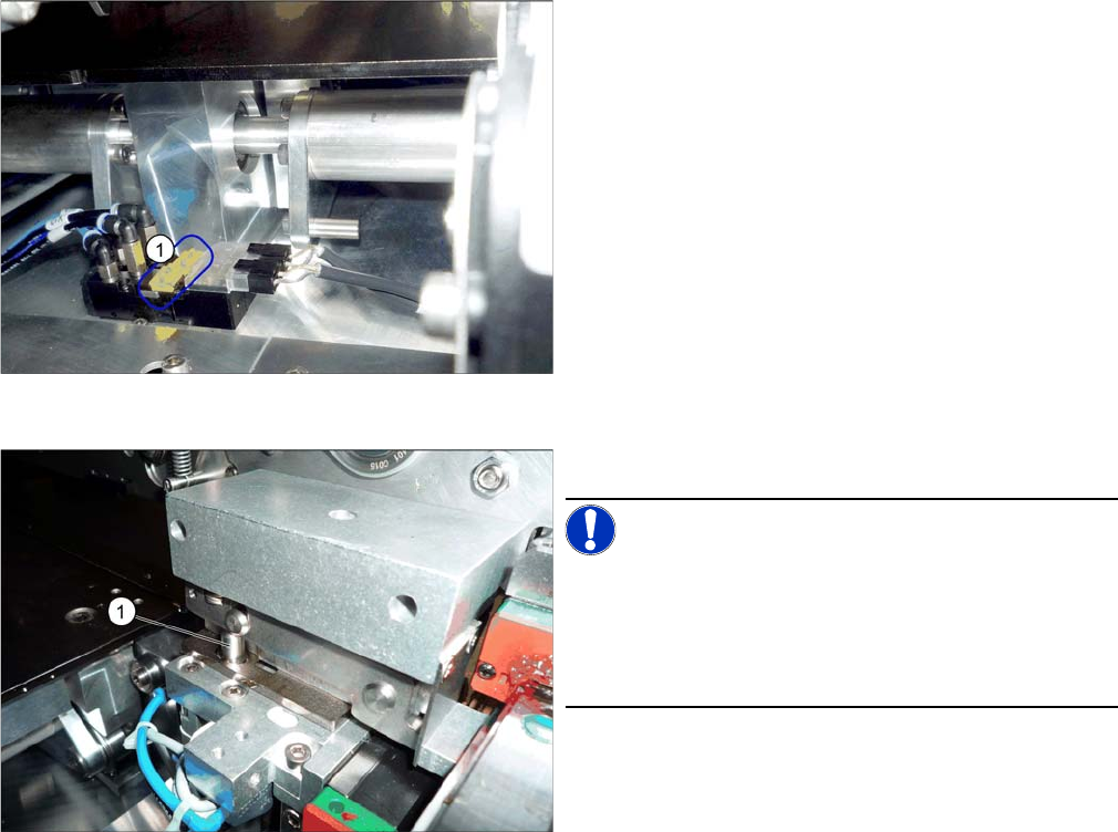
► Operate the solenoid valves (individually if needed)
using the yellow slide switches (1). This moves the
cylinders out, which then loosen the clamps.
► Make sure that all side cylinders (1) have engaged.
NOTICE!
The adjustment units need to be positioned under the
conveyor side so that all engage at the same time. If this
is not possible, check the parallelism of the adjustment
units. If these are OK, the conveyor side may be distort-
ed. In this case, call the SIPLACE Service team.
► Carefully pull on the width adjustment belt to move
the conveyor side.
► Repeat these steps if needed for any other conveyor
sides.
Service Work
3.6.1 Loosening the Conveyor Side Clamps Conveyor
Service Manual SIPLACE SX4/DX4 97
3.6.1.2
3.6.1.2 Moving the Conveyor Sides by Manually Releasing the Side Clamps
Moving the Conveyor Sides by Manually Releasing the Side Clamps
0220 - Parts etc. - SXDX4
Parts, equipment and tools
▪ Depending on your clamping version, you may need the following per side:
3x ISO4762-M3x35-A2-70 [03043114-xx] or
3x ISO8734-3x30-A-ST [03015760-xx]
Procedure
► Move the conveyor sides to a position which gives you good access to the clamps.
► Switch off the machine, disconnect it from the power supply and secure it to prevent unauthorized
reactivation. Observe the instructions in section "1.2 Preparatory Work..." [ ➙ 12].
► Repeat these steps for all clamps on the sides concerned.
NOTICE
Marking the starting positions
After completing this task, it is helpful to move the conveyor sides back to their approximate
starting positions.
► You may want to mark the current positions of the conveyor sides.
Do not mark the clamping surface or the guide rails.
CAUTION
Loosen all clamps
You always need to loosen all clamps for one conveyor side.
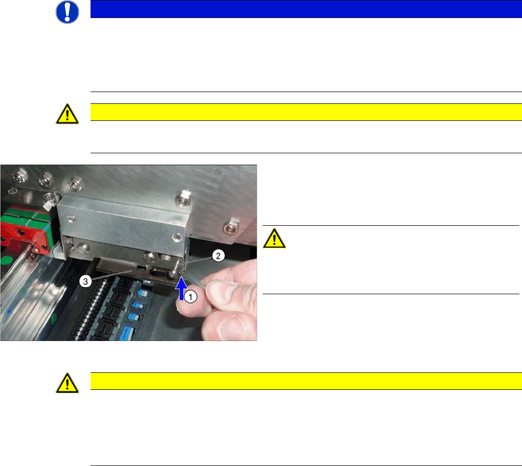
► Loosen the conveyor side clamps.
To do this, press the clamp (1) (e.g. with a screwdriv-
er) upwards and turn or insert a screw (M3x16) into
the hole (2).
CAUTION!
Make sure that you do not distort the guide plate (3). If
you do, this could lead to problems with recognizing the
position of the conveyor side.
CAUTION
Always loosen all clamps for one conveyor side!
► Always loosen all clamps for one conveyor side!
SX1/SX2/DX1/DX2: 2 clamps per conveyor side
SX4/DX4/X series S: 3 clamps per conveyor side.
► If you do not loosen all clamps for the conveyor side, this could be easily damaged.

Service Work
Conveyor 3.6.1 Loosening the Conveyor Side Clamps
98 Service Manual SIPLACE SX4/DX4
You can now move the sides.
Restoring the clamp
► Follow the removal instructions in reverse order for installation. Also observe the following instruc-
tions:
CAUTION
Moving the sides
► When the clamp is manually loosened, make sure that you only move the conveyor sides
by pushing against the clamping units.
► Make sure that you always move the conveyor sides parallel.
► Take care not to distort or trap the conveyor sides when pushing!
CAUTION
Installation instructions
► After completing the work, push the conveyor sides back into their approximate starting po-
sition.
► Make sure that the conveyor sides are back in their original positions after switching on.
► Perform a reference run.
► Perform side calibration for the fixed side on the left and right. If you do not, not all conveyor
sides will be calibrated.
This calibration is needed to ensure that the conveyor sides are positioned correctly.
► Conveyors for SX1/SX2 V2 only: calibrate the PCB sensors.
► Use a board to test the parallelism. This board must be transported evenly through the en-
tire conveyor. (See also Setting the Parallelism of the Conveyor Sides)
► Re-establish the original conveyor configurations:
For more information, go to Service menu - Conveyor configuration - Set options for con-
veyor fixed rail.
Select one of the positions and click on the Adjust configuration button.
Then reset the conveyor sides to the previous configuration.