SIPLACE-SX4-DX4-用户手册.pdf - 第281页
Description of the circuit boards 6.2.3 Vision board spread spectrum HCU [0306728 9-xx] Gantry Service Manual SIPLACE SX4/DX4 281 LED [03067289-02] Dip switch S1 [03067289-02] 6.2.3.1 6 . 2 . 3 . 1 D I P S w it c h o n t…
Description of the circuit boards
Gantry 6.2.3 Vision board spread spectrum HCU [03067289-xx]
280 Service Manual SIPLACE SX4/DX4
7-segment display V2 [03055069-05]
7-segment display V12 [03055069-05]
Dip switch S1 [03055069-05]
6.2.3
6.2.3 Vision board spread spectrum HCU [03067289-xx]
Vision board spread spectrum HCU [03067289-xx]
03067289-02
Display Status Description
Decimal point Flashes HCU2 OK
Display Status Description
Decimal point Flashes HCU1 OK
Switch Status Signal name Description
Gantry 2 Gantry 4
S1.1 OFF/ON Gantry_ID0 ON ON
S1.2 OFF/ON Gantry_ID1 OFF ON
S1.3 OFF COM_BOOT_HCU ON: set HCU to bootstrap mode
S1.4 OFF RESET_HCU2 ON: Reset HCU2
S1.5 OFF RESET_HCU1 ON: Reset HCU1
S1.6 OFF FAN Not used
S1.7 OFF DCDC_OFF ON: Reset, when not all the voltages are pre-
sent
S1.8 OFF HCU_1_2 Not used
Description of the circuit boards
6.2.3 Vision board spread spectrum HCU [03067289-xx] Gantry
Service Manual SIPLACE SX4/DX4 281
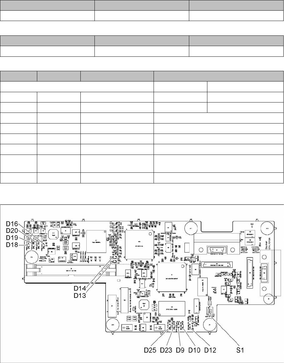
LED [03067289-02]
Dip switch S1 [03067289-02]
6.2.3.1
6.2.3.1 DIP Switch on the Vision Board (Digital Version 02)
DIP Switch on the Vision Board (Digital Version 02)
* Not all gantries may be available, depending on the machine type.
LED Color Status Signal name Description
D9 GN ON LED_XC_OK RUN
D10 RD ON LED_XC_ERR ERROR
D12 RD ON XC_RESET RESET
D13 GN ON IO/LVDS51P PCB camera active
D14 GN ON IO/LVDS51N CO camera active
D16 GN ON P12VCAM_I +12VDC for camera
D18 GN ON P5VCAM +5VDC for camera
D19 GN ON P2.5VCAM + 2.5 VDC for camera
D20 GN ON P3.3VCAM + 3.3VDC for camera
D23 GN ON P5V +5VDC
D25 GN ON P15V +15VDC
Switch Status Signal name Description
S1.1 OFF HW_RESET ON: RESET CAN controller
S1.2 OFF CAN_ID Not used
S Gantry* Comments
1 2 3 4
1 OFF OFF OFF OFF Reset - CAN processor
2 OFF ON OFF ON PID0 address switch 1 -> gan-
try
3OFF OFF ON ONPID1 address switch 2 -> gan-
try
4 OFF OFF OFF OFF CAN R - switch for the terminal
resistor on the CAN bus
5ON ON ON ONSpeed: ON = 1 Mbit/s, OFF =
500 Kbit/s
6ON ON ON ONCAN ID - for X machine ON
Description of the circuit boards
Gantry 6.2.4 X base adapter C&P [03045647-xx]
282 Service Manual SIPLACE SX4/DX4
6.2.4
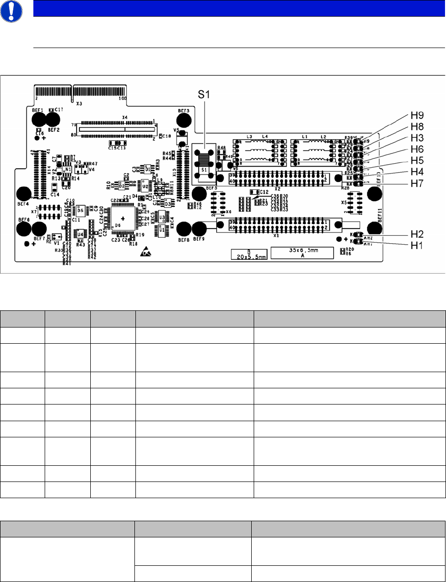
6.2.4 X base adapter C&P [03045647-xx]
X base adapter C&P [03045647-xx]
This board is used for C&P20x and CPP heads on X series S and SX4/DX4 machines.
Version 05
03045647-05
LED [03045647-05]
Switch S1 [03045647-05]
Switch S1 sets the link voltage for the Z axis
If the setting is incorrect, no damage will be done but an HCU error message will be issued.
NOTICE
C&P20 P
The X basis adapter needs at least function state 08 for the C&P20 P head.
LED Color Status Signal name Description
H1 GN ON CO_SENSOR CO sensor active
H2 GN ON - The programming plug for the HCU is con-
nected
H3 RD ON FPGA_TEST_6 1.5V power supply error
H4 RD ON FPGA_TEST_2 3.3V power supply error
H5 RD ON FPGA_TEST_4 5V power supply error
H6 RD ON FPGA_TEST_1 15V power supply error
H7 RD ON FPGA_TEST_3 DP power supply error, temp. without func-
tion
H8 RD ON FPGA_TEST_5 24V power supply error
H9 RD ON POWERFAIL_LOCAL PowerFail on circuit board
Switch Status Function
S1 40V Intermediate link voltage for Z axis -->
C&P20
150V Intermediate link voltage for Z axis --> CPP