SIPLACE-SX4-DX4-用户手册.pdf - 第42页
Service Work Electrical System 3.2.6 Replacing the Rectifiers (U1 to U3, U20 to U24) 42 Service Manual SIPLACE SX4/DX4 3.2.6 3 . 2 . 6 R e p la c in g t h e R e c t if ie r s ( U 1 t o U 3 , U 2 0 t o U 2 4 ) Replacing t…
Service Work
3.2.5 Replacing the AC/DC Converter (Pulsed Power Packs A5 to A8) Electrical System
Service Manual SIPLACE SX4/DX4 41
Removal
► Switch off the machine, disconnect it from the power supply and secure it to prevent unauthorized
reactivation. Observe the instructions in section "1.2 Preparatory Work..." [ ➙ 12].
► Unplug all connections to the module. You may want to mark their positions, to make clear assign-
ment easier later on.
Installation
► Follow the removal instructions in reverse order for installation. Also observe the following instruc-
tions:
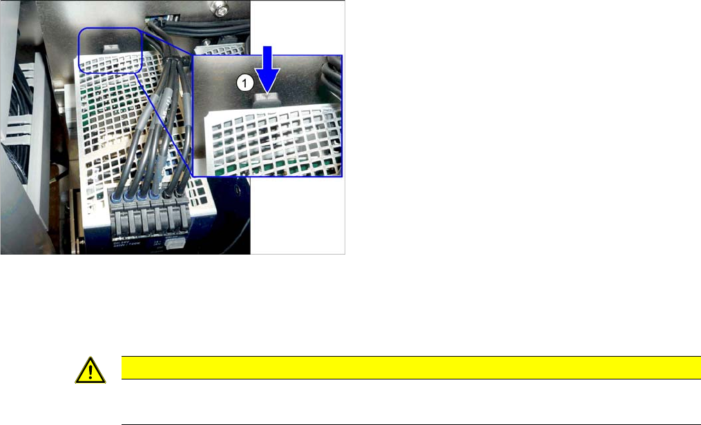
► To release the module, press the lever (1) at the back
of the module down and then pull the module off the
rail.
CAUTION
Installation instructions
► Set the voltage. (See "5.2.2 Setting the Voltage on the Pulsed Power Packs" [ ➙ 234])
Service Work
Electrical System 3.2.6 Replacing the Rectifiers (U1 to U3, U20 to U24)
42 Service Manual SIPLACE SX4/DX4
3.2.6
3.2.6 Replacing the Rectifiers (U1 to U3, U20 to U24)
Replacing the Rectifiers (U1 to U3, U20 to U24)
Parts, equipment and tools
▪ U1, U3: rectifier S101-B6U 160-08 [00341246-xx]
▪ U2: rectifier S61-B2U 28-10 [03080931-xx]
▪ U20 to U24: rectifier S61-B2U 28-04 [03079959-xx]
▪ Silicon-free heat-conductive paste (not electrically conductive)
Thermal conductivity 1.0 W/mK
Dielectric strength 40kV/mm
Temperature range -40°C to +200°C
Flash point >280°C
Suggested supplier: Bürklin OHG, order number 80 B 531
Overview
Removal
► Switch off the machine, disconnect it from the power supply and secure it to prevent unauthorized
reactivation. Observe the instructions in section "1.2 Preparatory Work..." [ ➙ 12].
► Loosen the screws fastening the cover and swing the cover towards the front. The pulsed power
packs are fitted to the cover. These are swung open together with the cover.
► Unplug all connections to the rectifiers. You may want to mark their positions, to make clear assign-
ment easier later on.
► Loosen the screws fastening the rectifier and remove the rectifier.
Installation
► Follow the removal instructions in reverse order for installation. Also observe the following instruc-
tions:
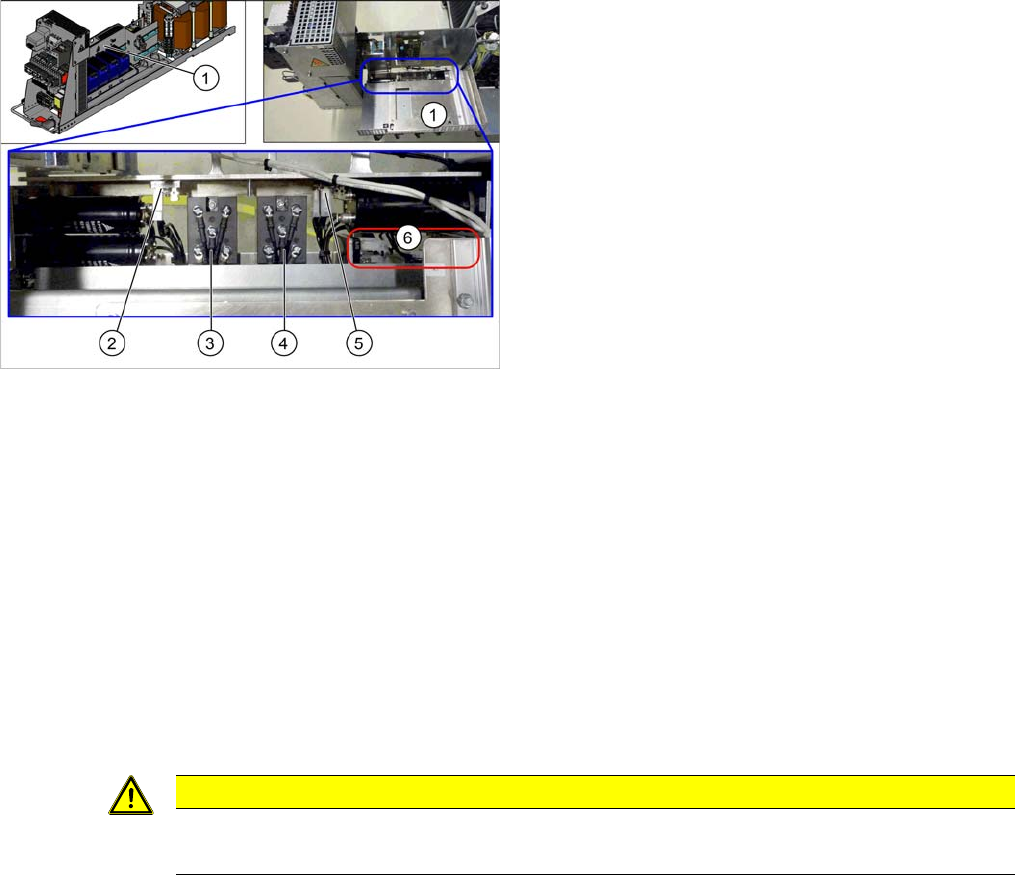
1. Cover
2. Rectifier U24
3. Rectifier U3
4. Rectifier U1
5. Rectifier U2
6. Rectifier U20 to U23
CAUTION
Installation instructions
► Apply a heat-conductive paste between the metal frame and the rectifier.
Service Work
3.2.7 Replacing the Load Add Circuit (A4) [03094585Sxx] Electrical System
Service Manual SIPLACE SX4/DX4 43
3.2.7
3.2.7 Replacing the Load Add Circuit (A4) [03094585Sxx]
Replacing the Load Add Circuit (A4) [03094585Sxx]
Parts, equipment and tools
▪ FBG dyn. load add circuit intermediate cycle [03094585Sxx]
Overview
Removal
► Switch off the machine, disconnect it from the power supply and secure it to prevent unauthorized
reactivation. Observe the instructions in section "1.2 Preparatory Work..." [ ➙ 12].
► Loosen the screws fastening the cover and swing the cover towards the front. The pulsed power
packs are fitted to the cover. These are swung open together with the cover.
► Unplug all connections to the load add circuit. You may want to mark their positions, to make clear
assignment easier later on.
► Loosen the screws fastening the load add circuit and remove it.
Installation
► Follow the removal instructions in reverse order for installation.
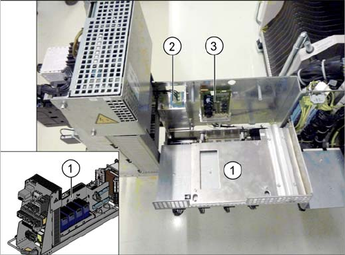
1. Cover
2. Line filter (Z1)
3. Load add circuit (A4)