SIPLACE-SX4-DX4-用户手册.pdf - 第191页
Service Work 3.12.2 Replacing the Micro Fu se [0303338 7-XX] Docking Station for X-Series Component Trolley Service Manual SIPLACE SX4/DX4 191 3.12.2 3 . 1 2 . 2 R e p la c in g t h e M ic r o F u s e [ 0 3 0 3 3 3 8 7 -…
Service Work
Docking Station for X-Series Component Trolley 3.12.1 Replacing the Power Pack [03025938-XX]
190 Service Manual SIPLACE SX4/DX4
3.12
3.12 Docking Station for X-Series Component Trolley
Docking Station for X-Series Component Trolley
3.12.1
3.12.1 Replacing the Power Pack [03025938-XX]
Replacing the Power Pack [03025938-XX]
Parts, equipment and tools
▪ Circuit diagram folder for your machine
Overview
Removal/installation
► Reconnect the connection leads and install the new power pack.
► Connect the power pack connection cable and press the ON/OFF button to switch on.
► Set the output voltage of the power pack to 26.8 V (+/- 0.5 V) at terminals nine and twelve.
► Refit the cover.
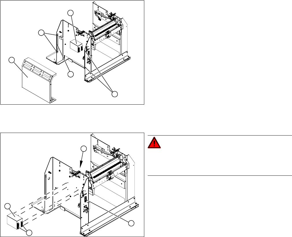
1. Cover
2. Bar for clamping the cover
3. Fastening screws
4. Power pack
► Loosen the four screws (3) fastening the cover (1).
The cover is clamped in place with the help of the bar
(2).
► Pull the cover out of the docking station.
► Take care not to damage the earth connection.
4
3
1
3
2
DANGER!
Switch off the voltage supply
Press the ON/OFF button (1) to switch off, and discon-
nect the power supply.
► Loosen the four screws (2) fastening the power pack
(3) on the inside of the docking station.
► Label the connection leads and disconnect these
from the terminal strip (4).
4
3
1
2
Service Work
3.12.2 Replacing the Micro Fuse [03033387-XX] Docking Station for X-Series Component Trolley
Service Manual SIPLACE SX4/DX4 191
3.12.2
3.12.2 Replacing the Micro Fuse [03033387-XX]
Replacing the Micro Fuse [03033387-XX]
Parts, equipment and tools
▪ Microfuse [03033387-xx]
Overview
Replacing the micro switch
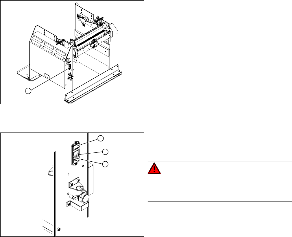
► Open the cover (1) on the micro fuse.
► Pull out the micro fuse.
► Insert the new micro fuse and close the cover (1).
► Connect the connection cable (3) and press the ON/OFF button to switch on (2).
1. Position of micro fuse (T 8.0 A)
1
1. Position of micro fuse (T 8.0 A)
2. ON / OFF switch
3. Power supply plug
DANGER!
Switch off the voltage supply
Press the ON/OFF button (2) to switch off, and discon-
nect the power supply (3).
1
3
2
Service Work
Docking Station for X-Series Component Trolley 3.12.3 Replacing the Locking Unit Short-Stroke Cylinder [03034831-XX]
192 Service Manual SIPLACE SX4/DX4
3.12.3
3.12.3 Replacing the Locking Unit Short-Stroke Cylinder [03034831-XX]
Replacing the Locking Unit Short-Stroke Cylinder [03034831-XX]
Parts, equipment and tools
▪ Short-stroke cylinder [03034831-xx]
Overview
Removal
Installation
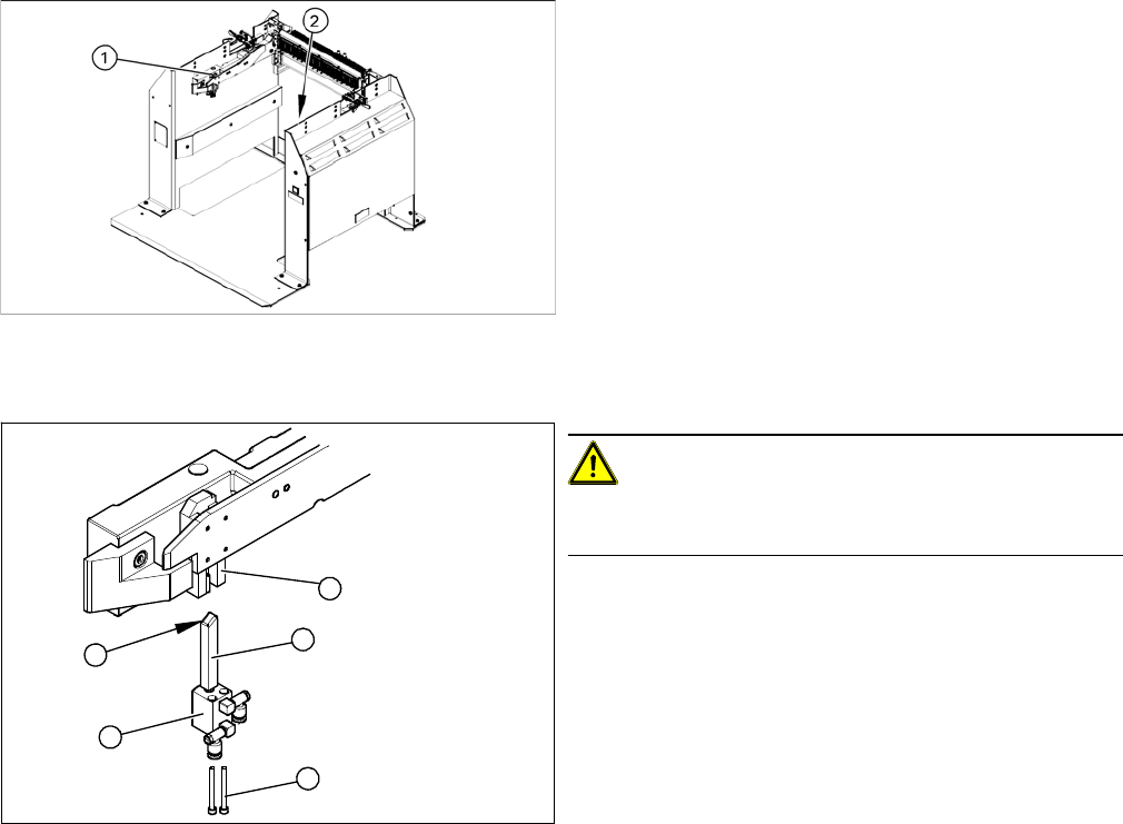
► Install the locking slider (3) on the new short-stroke cylinder (2).
► Reconnect to the compressed air supply.
► Clean the locking sliders (3) and the guidance block (5) with a clean, lint-free cloth and lubricate both
slightly with Unisilikon.
► Move the locking slider (3) into the guidance block, so that the beveled side (4) is pointing to the front
(in the direction of travel). This is important when moving the component trolley in.
► Fit the short-stroke cylinder with the two fastening screws.
► Switch the compressed air supply on again and check that the left and right locking sliders move out
at the same time.
► If necessary, adjust the throttle valve (6) on the short-stroke cylinder.
1. Installation position of left locking unit
2. Installation position of right locking unit
CAUTION!
Risk of injury when disconnecting pressurized com-
pressed air lines.
► Switch off the compressed air supply.
► Loosen the two screws (1) fastening the short-stroke
cylinder (2).
► Pull the short-stroke cylinder (2) and the locking slider
(3) downwards and out of the guidance block (5).
► Loosen the pneumatic connections on the short-
stroke cylinder.
► Unscrew the locking slider (3) from the short-stroke
cylinder (2).
5
1
4
3
2