SIPLACE-SX4-DX4-用户手册.pdf - 第58页
Service Work Control 3.3.1 Replacing the Control Computer BoxPC 58 Service Manual SIPLACE SX4/DX4 Removal ► Switch off the machine, disconnec t it from the po wer supply and secure it to prev ent unauth orized reactivati…
Service Work
3.3.1 Replacing the Control Computer BoxPC Control
Service Manual SIPLACE SX4/DX4 57
3.3
3.3 Control
Control
3.3.1
3.3.1 Replacing the Control Computer BoxPC
Replacing the Control Computer BoxPC
Parts, equipment and tools
▪ SX4: BoxPC 827B, 1 GB RAM [03069632-xx]
▪ DX4: BoxPC 627B with hotlink cable, 2 GB RAM [03055300-xx]
▪ X series S: Control computer BoxPC 827C [03094732-xx] or
Control computer BoxPC 627C [03094731-xx] (as option for 3D coplan)
Overview
CAUTION
Plug-in card
The BoxPC is supplied without the following parts. These must be removed from the old Box
PC and fitted in the new one or ordered as new parts.
► Hotlink interface PCI-A24-K01 (1x, with stationary camera 2x) [03052135-xx]
► CAN card PowerCAN-PCI (1x) [03052590-xx]
► Working memory SO-DIMM DDR2 667 1024MB (1x)
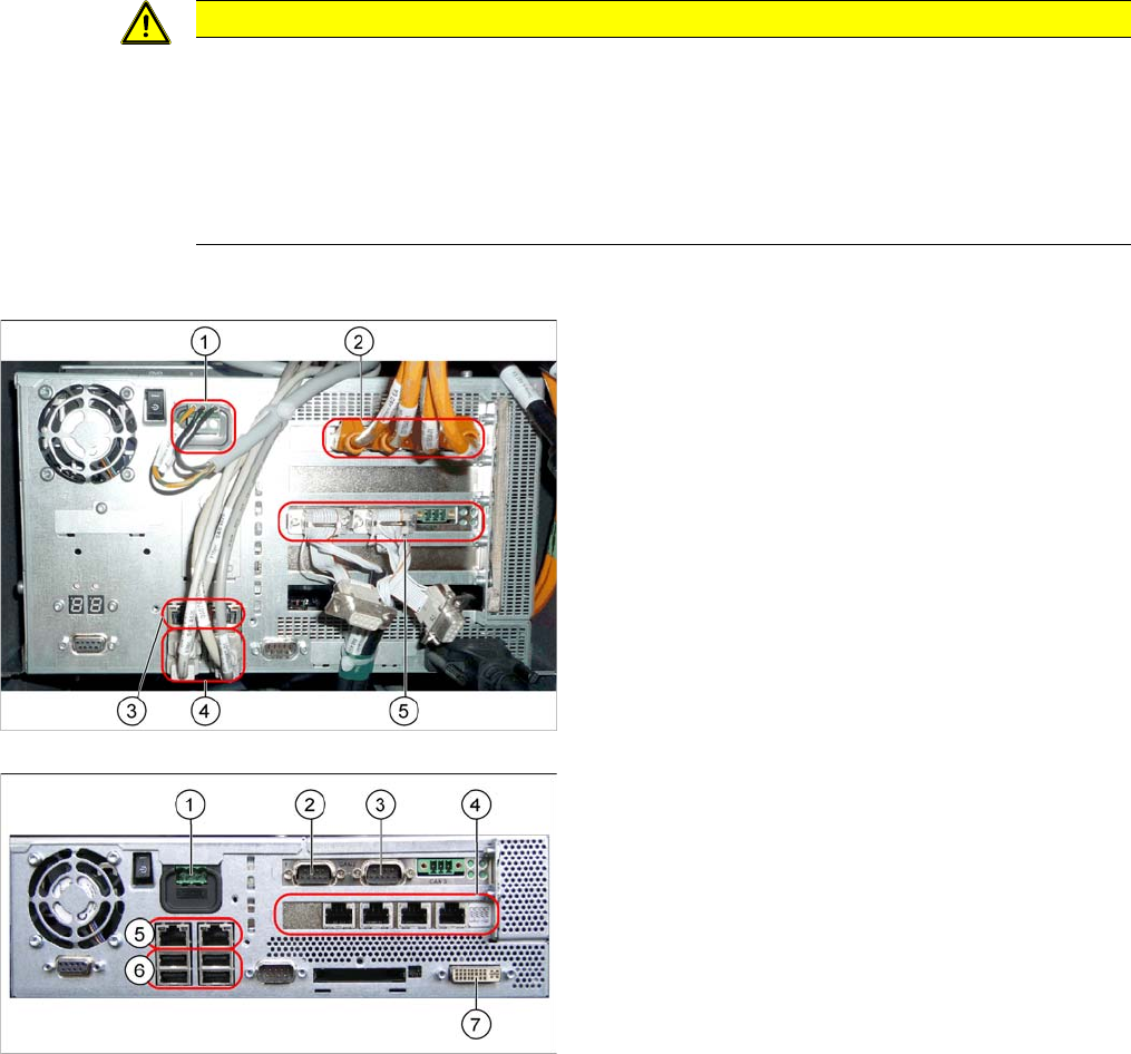
BoxPC 827C (SX4/DX4, X series S)
The BoxPC is located in a rack unit between locations 1
and 2.
1. Power supply
2. Hotlink interface
Depending on the placement heads used, there are
either one or two hotlink interfaces fitted.
One hotlink interface: if only C&P20 heads are fitted.
Two hotlink interfaces: all other placement head con-
figurations
3. LAN connections
4. USB connections
5. CAN card
Example of BoxPC 627B
BoxPC 627C (SX1/SX2/DX1/DX2, 3D coplan)
1. Power supply DC 24 V
2. CAN 1
3. CAN 2
4. Hotlink card
5. LAN connections
6. USB connections
7. DVI/VGA monitor connection
Service Work
Control 3.3.1 Replacing the Control Computer BoxPC
58 Service Manual SIPLACE SX4/DX4
Removal
► Switch off the machine, disconnect it from the power supply and secure it to prevent unauthorized
reactivation. Observe the instructions in section "1.2 Preparatory Work..." [ ➙ 12].
► Unplug all press-fit connections to the BoxPC. Mark their positions, to make clear assignment easier
later on.
► The BoxPC is fixed to the machine with Velcro. Release the BoxPC from the Velcro and remove it
from the machine.
Installation
► Follow the removal instructions in reverse order for installation. Also observe the following instruc-
tions:
CAUTION
Installation instructions
► The new BoxPC is supplied without a CAN card, hotlink interface or memory extension to
2 GB. You will need to take these from the old BoxPC and fit them in the new one. (See
"3.3.2 Replacing the CAN Card [03079973-xx]" [ ➙ 59],
"3.3.3 Replacing the Hotlink Interface Card [03052135-xx]" [ ➙ 60] and
"3.3.4 Replacing the BoxPC Memory Extension [03086337-xx]" [ ➙ 61])
► The BoxPC needs to be installed after it has been fitted. (See the following instructions)
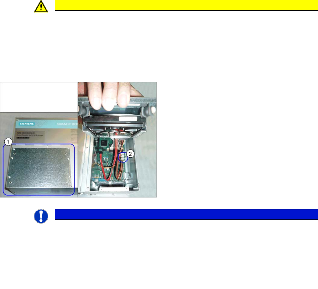
Hotlink interface power cable
► The hotlink interface power cable [03042074-xx] (2)
needs to be taken from the old BoxPC and fitted in the
new one. To gain access to this cable, loosen and
open the cover (1) on the hard drive.
NOTICE
Installing the BoxPC
► The BoxPC needs to be installed after it has been fitted. Read the relevant installation
guide:
- "Windows Embedded Standard 7" [00197366-xx]
- "Windows XP Embedded" [00196737-xx]
► BIOS update and setting images are no longer included on the station software CD.
The CDs for the BIOS settings are only available via the SIPLACE Software Download
Center (SDC).

Service Work
3.3.2 Replacing the CAN Card [03079973-xx] Control
Service Manual SIPLACE SX4/DX4 59
3.3.2
3.3.2 Replacing the CAN Card [03079973-xx]
Replacing the CAN Card [03079973-xx]
Parts, equipment and tools
▪ 1x CAN card COM168V2-PCI [new: 03079973-xx] (old: [03052590-xx])
Overview
The CAN card is installed in the BoxPC.
Removal
► Switch off the machine, disconnect it from the power supply and secure it to prevent unauthorized
reactivation. Observe the instructions in section "1.2 Preparatory Work..." [ ➙ 12].
► Dismantle and remove the BoxPC from the machine.
(See "3.3.1 Replacing the Control Computer BoxPC" [ ➙ 57])
► Loosen the two screws fastening the cover of the BoxPC and open the cover.
► Loosen the screw fastening the CAN card and remove the CAN card.
Installation
► Follow the removal instructions in reverse order for installation. Also observe the following instruc-
tions:
CAUTION
Installation instructions
► Make sure that the plug-in card is correctly fitted into its slot.