SIPLACE-SX4-DX4-用户手册.pdf - 第210页
Service Work Manual Table (DX4) 3.13.8 Replacing the Empty-Tape Duct Assembly 210 Service Manual SIPLACE SX4/DX4 3.13.8 3 . 1 3 . 8 R e p la c in g t h e E m p t y - T a p e D u c t A s s e m b ly Replacing the Empty-Tap…
Service Work
3.13.7 Replacing the Centering Bar Manual Table (DX4)
Service Manual SIPLACE SX4/DX4 209
3.13.7
3.13.7 Replacing the Centering Bar
Replacing the Centering Bar
Parts, equipment and tools
Select the correct spare part:
Overview
Removal
► Loosen the four fastening screws on the front side.
► Pull the centering bar off the locating pins.
Installation
► Follow the removal instructions in reverse order for installation. Also observe the following instruc-
tions:
Machine type Designation Item No.
DX4 Stop rail 40/2-fold 03082777-xx
DX1/DX2 Stop rail 60/2-fold 03081975-xx
Stop rail 30/2-fold 03082572-xx
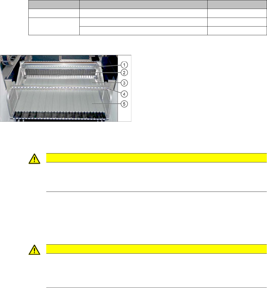
Manual table (using example of DX1/DX2)
1. Centering bar
2. FCU
3. Front part
4. Back part
CAUTION
Front and back section must be fitted
The centering bar may only be released if both the front and back sections are fixed inside the
machine. The table could be distorted otherwise. The possible consequence would be prob-
lems with feeder recognition.
CAUTION
Installation instructions
► Before installation, clean the centering pins on the sides of the centering bar.
► Make sure that the centering bar is not tensioned.
► Check that all feeders fit easily into the centering and are not subjected to tension.
Service Work
Manual Table (DX4) 3.13.8 Replacing the Empty-Tape Duct Assembly
210 Service Manual SIPLACE SX4/DX4
3.13.8
3.13.8 Replacing the Empty-Tape Duct Assembly
Replacing the Empty-Tape Duct Assembly
► Please refer the instructions in section "3.10.6 Replacing the Empty-Tape Duct Assembly
[03052576-xx]" [ ➙ 177].
3.13.9
3.13.9 Replacing the Complete Mounting Frame
Replacing the Complete Mounting Frame
Parts, equipment and tools
Select the right mounting frame:
▪ Rubber mallet
Overview
Removal
► Dismantle the back section of the manual table. (See "3.13.2 Removing the Back Section of the Man-
ual Table" [ ➙ 201])
Machine type Designation Item No.
DX4 COT insert MT 40 03082689-xx
DX1/DX2 COT insert MT 60 03081574-xx
COT insert MT 30 03082560-xx
Manual table (using example of DX1/DX2)
1. Centering bar
2. FCU
3. Front part
4. Back part
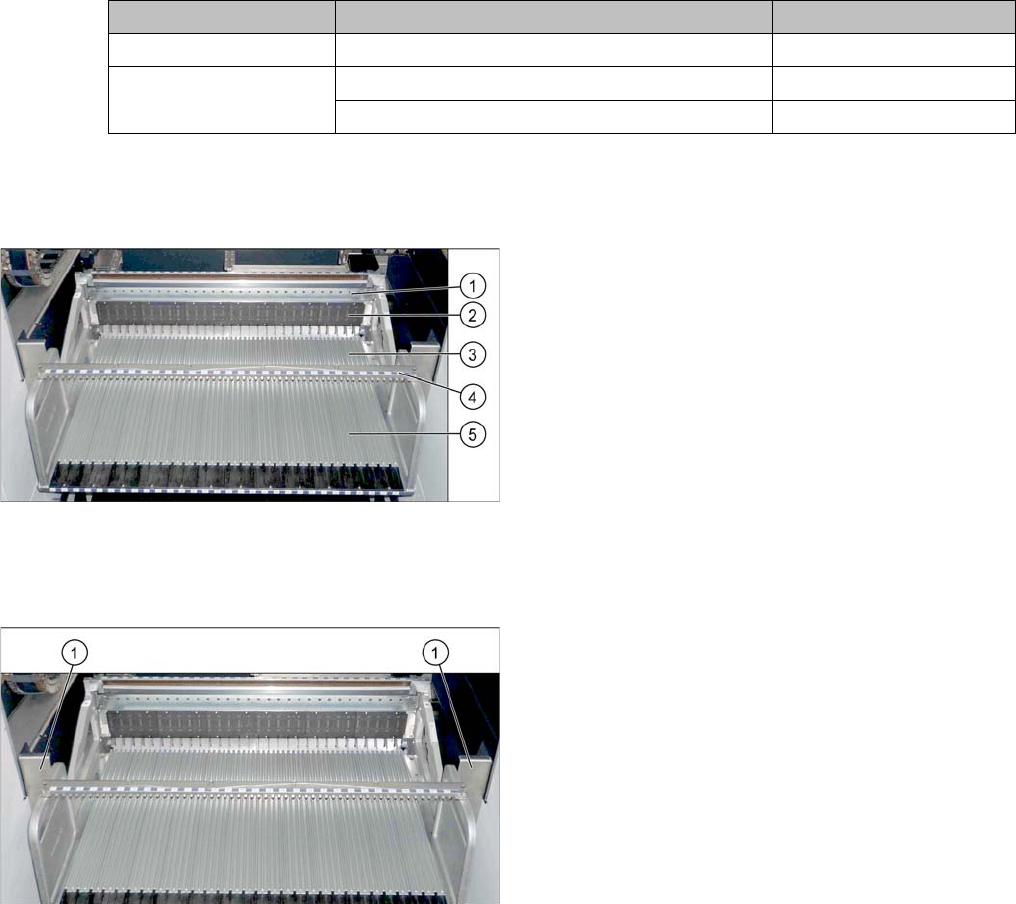
► For better access, dismantle the two protective
plates (1) on the side of the mounting frame.
Service Work
3.13.9 Replacing the Complete Mounting Frame Manual Table (DX4)
Service Manual SIPLACE SX4/DX4 211
► Dismantle the cutter. (See the section about the cutter)
Installation
► Follow the removal instructions in reverse order for installation.
See also
3.9.1 Replacing the Cutter on the COT Insert [03066690-xx] [ ➙ 154]
3.13.3 Removing the Front Section of the Manual Table [ ➙ 202]
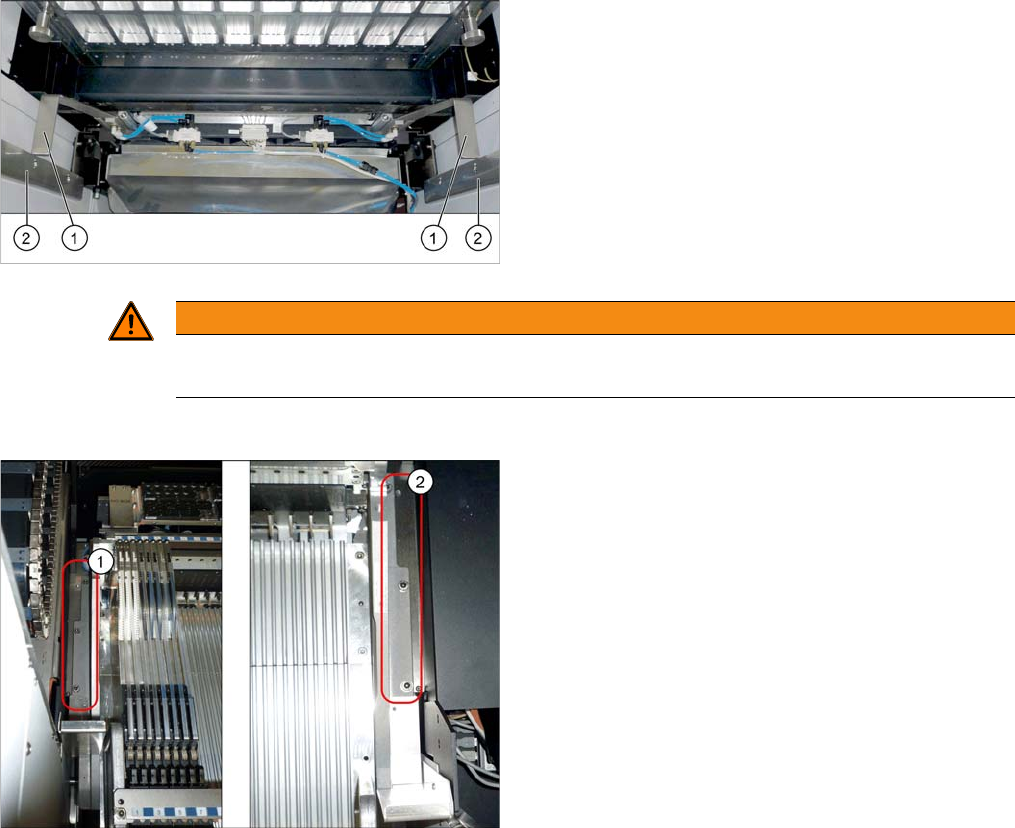
► Dismantle the stoppers (1).
You may need to lower the cutter onto the support
plates (2). (See Replacing the Cutter [03063781Sxx])
WARNING
Do not remove the front part
Do not dismantle the front section here as the frame would otherwise be unstable.
► Loosen the fastening screws on the left (1) and
right (2) and remove the mounting frame.